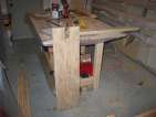
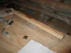
Building strongback rails
posted 2004 Mar 30
Starting with a 4'x8' sheet of 5/8" ACX plywood, I started cutting
out all the pieces for the centre and side strongback rails.
The sides are easy - cut off 1" at the end, and then cut:
- four strips 1 15/16" wide
- four strips 1 11/16" wide
While you're at it, cut another two strips 1 15/16" wide (and the full
96" long) for the centre rail.
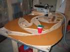
Next up is cutting everything for the centre rail. This is a
little more complicated, because the pieces can't be flipped over to
get the "A" side of the plywood to be on the outside of the finished
piece (if you care). The best way I could think of to do it is to
flip over the plywood between cutting each of the two "L" pieces
required (pieces D & E).
Here is the picture I used to make all my first cuts (original Visio diagram).
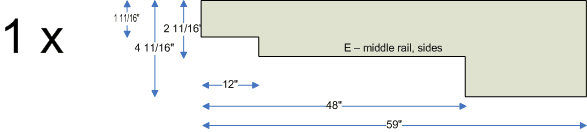
Then, one of the "short L's" and one of the "long L's" need to be
further cut down, to add a 12" divit on the end, like this:
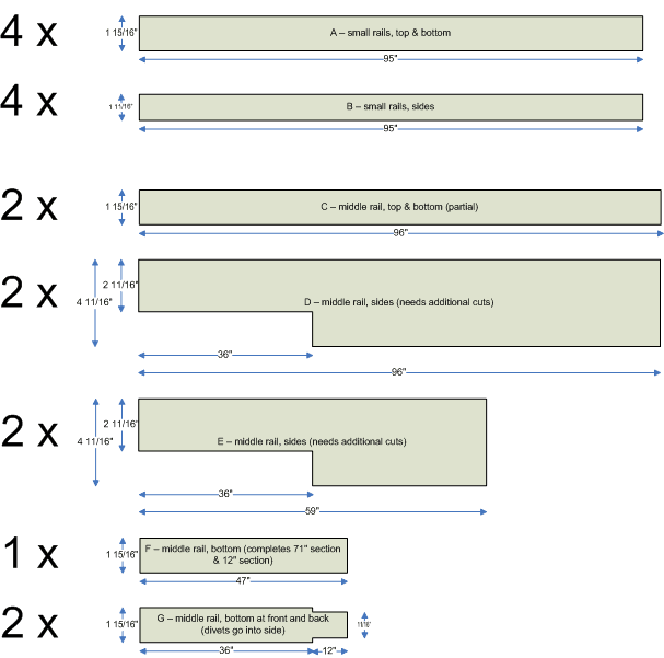
Here is the cut list:
| | item | qty | width, in | length, in |
|---|
| A | small rails, top & bottom | 4 | 1 15/16 | 95 |
| B | small rails, sides | 4 | 1 11/16 | 95 |
| C | middle rail, top & bottom | 2 | 1 15/16 | 96 |
| D | middle rail, long L, sides (needs additional cuts) | 2 | 4 11/16, 2 11/16 for 36" | 96 |
| E | middle rail, short L, sides (needs additional cuts) | 2 | 4 11/16, 2 11/16 for 36" | 59 |
| F | middle rail, bottom (completes 71" section & 12" section) | 1 | 1 15/16 | 47 |
| G | middle rail, bottom at front and back (divits go between sides) | 2 | 1 15/16, 11/16 for 12" | 48 |
All of this I cut with my trusty circular saw, using the rip
fence to ensure the straight lines were really straight.
With all of the pieces cut, I did the work to modify the last 12"
of what will be the stern of the strongback - cut it down to 1 11/16"
for the last 12 inches. I then glued and screwed it all together.
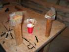
The only thing I found when I was gluing it up was that it is
important to ensure that everything stayed straight. The plywood has
a tendency to bow, usually towards the flat A (finished) surfaces (not
the edges). On the centre rail, when I screwed the top down into the
edges, I found that the tops and/or sides "moved" slightly. The
pieces for the centre rail are arranged like this  . I
screwed the top onto the sides at the ends like this
. I
screwed the top onto the sides at the ends like this  ,
so the sides would stay vertical, and then screwed the top down over
the red area. What happened was the black gap grew tighter, causing
the rail to veer off to one side (the top in the image). I wound up
cutting out a sliver of the edge in the black gap, so the rail
wouldn't veer as much. Getting these things straight is critical.
,
so the sides would stay vertical, and then screwed the top down over
the red area. What happened was the black gap grew tighter, causing
the rail to veer off to one side (the top in the image). I wound up
cutting out a sliver of the edge in the black gap, so the rail
wouldn't veer as much. Getting these things straight is critical.
[Update 2004 Oct 5: Greg mentioned in
mail that plywood was the wrong thing to use for the rail, because it
bows due to the stress of the layers on each other. I agree - using
chipboard would have ensured the rail was straight, which would make
alignment much easier.]
I also built sawhorses. The construction manual shows divits cut
from plywood, and Kayak shows sawhorses, so I compromised. I
screwed a divited piece of plywood into the end of sawhorses. The
sawhorses stop the entire assembly from falling forward or back. On the
website, Bram says that the short one should be 24" to the notch,
and 30" on the tall one ("People over 6 feet tall may want to make
them a bit higher"). Mine are 30" and 36" to the notch, respectively.
I used plain ol sawhorse
brackets to build the actual sawhorse, and made the legs 27 1/2"
and 30". About 4 inches is added to the top of the leg when it's all
assembled.
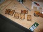
Building side rails, epoxying stations
posted 2004 Mar 22
I glassed the bevel blocks. At first I was going to get the glass
to stick to the 1/4" wide side of the bevel block, and I was using an
elastic and some plastic to try and get this to happen. But there
were a ton of air bubbles and I couldn't get everything to stay (even
as the epoxy kicked) and so I finally gave up and just put the cloth
along the top.
I also epoxied both sides of all the stations, so they would be
less likely to expand and contract with the changes in temperature and
humidity of the garage (Bram suggests this here).
Once cured, I aligned all the centerlines and waterlines of the
stations, and drilled a number of 3/8" holes through them. This way,
when I have all the stations aligned on the strongback, I can use a
laser level and ensure that the stations are all correctly
aligned.
I then wrapped (clear) packing tape around the edges. Using
something like fibre-reinforced tape might have been easier - it's no
fun pushing down the overhang on all the edges.
Finally, I cut out all the holes for the strongback rails in the
stations. I drilled holes to allow the jigsaw blade through, then cut
everything. I went a bit overboard - station 6, where the side rails
stop, I cut out the holes for the side rails anyway. I'll have to
epoxy the pieces back in.
[Update 2004 Oct 5: Once the holes are cut in all the
strongbacks, be sure to put the strongbacks back on the patterns to
ensure the holes were correctly positioned. This ensures that you've
cut the right spot. I didn't do this and should have, it would have
made things easier during alignment.]
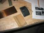
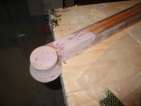
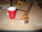
The spin block
posted 2004 Mar 17
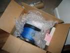
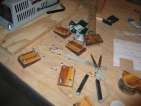
I shaped the bow piece and the spin block. The parts shipment also
arrived - so I've been poking through the box and trying to ensure
that all the bits and pieces are there.
For the bow piece, I sanded off some of the curved area, mostly to
remove the rough edges, but largely left it alone. It will mostly be
cut apart when it is installed on the hull anyway. I did sand the
flat edge flat, however, to ensure a good fit.
The spin block started out as 7 sheets of glued-up strips, each 3"
x 5". Once I had taken it out of the nails and sanded it down so
there was no epoxy left on the edges, it was a block 2" wide by 2 1/2"
tall, by 4 1/2" long. I took that piece and then worked it on the
bench sander to give it a nice shape, with plenty of
extra to handle the heavy loads of the spinnaker block that will be
bolted to it. I rounded the edges, and then glassed it - the first
attempt at glassing didn't go so well, so I pulled the glass off and
will try again with a better cut piece of glass.
As an intermission from the spin block, I cut down part of the
sheet of 4'x8' into the pieces that will be used as the strongback
rails. I really need a cut sheet, so I only did the simple pieces for
the side rails and top of the main rail. Having that (clean) sheet of
4x8 also let me spread out the pieces from the parts kit, so I could
ensure everything was there.
I did the last step on the centre rail - I drilled the holes for
the vang. I used a gadget I recently picked up. It's a flat piece of
plastic which holds a metal insert exactly vertical. The metal inserts
are sized for your drill bit. You hold the plastic flat to the
surface, and you'll get a hole very close to vertical. It worked
perfectly - the holes are dead on. I used a 7/32" bit - a 10-24 bolt
will fit in 3/16", but it drops into 7/32", without touching the
sides. I filled them with epoxy, drained, and pounded the tee-nuts
into the bottom (I also found out that using a paperclip works better
to grease the threads than a Q-tip. The paperclip leaves more grease
behind.)
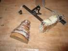
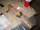
Spinnaker block, bow 'ball'
posted 2004 Mar 14
I completed the spin pole ring saddle. I sanded both edges to a
bevel of 23°, and the ends to 45°. I then glassed the top,
bottom and sides. When that cured, sanded off the excess and glassed
the ends.
With some of the excess epoxy/207 from the spin saddle, I put a
sealer coat on the bevel blocks. I also put a second layer on the
e-glass tape I wrapped around the bevel blocks. It flowed down to the
bottom a bit, but I think I can safely call these parts "done"
now.
I also sanded down the fairing compound on the vang pedestal and
coated the entire centre rail/vang pedestal in three coats of
epoxy/207/graphite. The second coat I didn't add enough graphite to
make it opaque, so I had to sand it down and put on another coat.
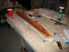
While I was waiting for everything to cure, I started work on the
spin block. For this piece, you need seven layers of wood, each layer
with grain running in opposite directions. Between each layer is
s-glass and epoxy/406 (and I added 403 as well). I glued up all the
little boards, and then using the same system as the centre rail
(nails in the tabletop) I layed up the block and weighted it down with
some paint cans.
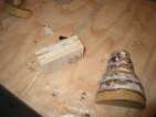
For the bow piece, you cut 6 pieces. 5.5" is the diameter of the
top piece, and 1.5" the diameter of the bottom edge of the bottom
piece. The top edge of that bottom piece (piece F) should have a
diameter of 2.1" - the bottom edge will be worked down to 1.5". The
grain should alternate directions between each piece, to reduce the
chance of splitting.
| piece | diameter, in | radius, in | grain |
|---|
| A | 5.5 | 2.75 (2 3/4) | — |
| B | 4.8 | 2.42 (2 7/16) | | |
| C | 4.1 | 2.08 (2 1/16) | — |
| D | 3.5 | 1.75 (1 3/4) | | |
| E | 2.8 | 1.42 (1 7/16) | — |
| F | 2.2 | 1.08 (1 1/16) | | |
| - | 1.5 | n/a | n/a |
Once all the pieces are cut, I just bonded them all together with
epoxy/406/403 and s-glass between the layers. The "tower" of blocks
wants to slide apart as it gets tall, so watch out!
Centreboard trunk and spinnaker pole ring saddle
posted 2004 Mar 07
More little stuff. I'm getting to the point where I do a bunch of
construction work and batch up all the epoxy work, so I can epoxy a
number of pieces at the same time. Saves on materials, I throw out
less leftover epoxy.
Here's this weekend's work:
- I bonded a cap to the centre rail/vang pedestal with an
epoxy/405 mixture.
- Glassed the bottom of the bevel blocks. I put disposable zinc
bolts into the tee-nuts to stop epoxy dripping through, covered the
bottoms in grease, and then faired them with epoxy/405 left over from
bonding the cap to the centre rail. Put s-glass on - I should have
then pressed the glass in by putting it glass side down on the
workbench, to make the bottom flat (pity I forgot). Covered it in
epoxy/207.
- Glassed the gudgeon block already on the transom bar with the
leftover 207. Doing this after bonding them together worked out well,
it makes it a bit easier than the glass for the standalone block,
because the draping glass sticks to the transom bar.
- Cut 1/2" wide strips of solid cedar for the centreboard trunk
ends. Wrapped them in a piece of scrap hybrid, painted on epoxy,
wrapped in plastic, clamped, let cure, and then painted again with a
second coat of epoxy (when the first became tack-free).
- Bevelled the back edge of the centre rail to match up to the
vang pedestal. This turned out perfectly, I'm happy with the results.
- Cut and bevelled a number of pieces for the centreboard
trunk.
- Glassed the unglassed parts of the centre rail. Getting the
glass to settle was tricky and I wound up using an elastic to keep the
glass pressed to the edge - and I should have used plastic to keep
them apart. Epoxy bonds to rubber nicely. With a triangle file and a
round file, however, I managed to rectify my mistake.
- Faired the vang pedestal.
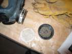
- Cut the spinnaker pole
ring saddle from a piece of 1" thick solid cedar. It started out
as 4" by 6", and I bevelled the bottom to match the top edge of
station 1. I then used the power sander to remove some stock for the
circular divit on the top - it should wind up to be a divit of 3 1/2"
diameter, about the diameter of a WEST System fairing container.
Bevel the sides in 23° and ends in 45°.
[Update 2004 Jul 28: it would have
been worth it to assemble the entire centreboard trunk at this point,
rather than when it had to be inserted in the hull. (instructions)
This way you work in a shop that has room rather than on a cramped
edge of your workbench.]
[Update 2004 Jul 29: also note that
Bram has a new insert
mechanism (local) which
is easiest to install when you are building the centreboard trunk.]
The centre rail
posted 2004 Mar 05
I cut the new vang pedestal in half, and then glassed both the
outer edge of the pedestal as well as the entire centre rail with
s-glass.
I also used 2" e-glass tape to glass the edges of the bevel
blocks. This required a bit of effort to ensure the glass stuck - I
painted the edges with epoxy/207, waited a while for it to get nice
and tacky. While I waited, I cut strips of e-glass tape to the right
length to wrap around the outer edges. Once tacky, I wrapped the
outside with the tape. The short edge doesn't need the tape form fit
along the vertical edge (which would cause the tape along the long
bottom side to not align), but the tape must form fit along the tall
vertical edge, which means that there are "tabs" along the bottom -
look here for what I
mean. With the remaining epoxy/207, I glassed one of the gudgeon
blocks - I'll go back and do the other one as well.
Once the epoxy had gelled up on the bevel blocks, I cut away the
overlap. The West
System instructions talk about using a sharp utility knife to cut
the edges and remove the overlap, but on such a small cut I found it a
lot easier to pull off the wet tape (once it was gelled) and cut with
scissors, and then cut the other side to match. Once you're used to
how to cut, it's easy to make the two edges match.
Once everything cured, I sanded away the excess and smoothed out
the edges. Next will be a second coat of epoxy, and glassing the
bottom surface.
I also cut the cap for the vang pedestal. I used the 3 1/2"
circle saw to get the starter shape, then mounted that on the drill to
get it down to the right size. I had problems with it turning oblong
(I botched one and had to do it again). What I wound up doing was
cutting a circle of the desired (bottom) radius, taking off a bunch of
material via the drill, and then getting the final size and shape by
holding the piece with the paper on top of it up against the disc
sander. This worked pretty well, you still have to be careful about
removing material too quickly.
Last up: I started cutting the parts for the centreboard trunk.
I aligned all the strips vertically in the trunk body, but the smaller
pieces I will align them horizontally. They seem to be providing
strength longitudinally, so horizontal strips seems to make more
sense.
Page 53 of 62
« First
…
«
51
52
53
54
55
»
…
Last »