Building bevel blocks
posted 2004 Feb 29
Did more catching up on the little bits this weekend, and more
work on the bevel blocks.
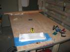
I glassed the backing blocks on the transom. To get the right
shape, I used a blank I had cut that turned out to be too small, but
was still cut to all the right angles. I laid it down on the glass
and traced it's outline, and then cut. There were a bunch of strands
of glass floating around, but it worked out ok. Once I had applied it
and the epoxy had cured, I used a file to take off the rough spots,
which worked out pretty well.
I sealed the holes in station 6 with some leftover epoxy. This
time, instead of putting a line of epoxy over the edge while the
station was vertical, I laid the station flat and painted the inside
edges. It made a lot less mess on the sides, and while I doubt it's
as good a seal (the spots with end-grain in particular could probably
use more), it's certainly cleaner.
I cut the transom bar to roughly the correct length. I centred
the bar on the transom, then scribed where the cut should be - then
added 1 1/2 inches outwards and cut there.
I shaped a new vang pedestal. Bram says here
that the top diameter is 2" and the bottom 3", and the pedestal I
first build had a flare maybe slightly less than 3" on the bottom. It
doesn't really have the "flare" I want on the bottom edge though, so I
built another one. I bonded together 6 layers of scrap bulkhead
material (I've got plenty of that ;-) with epoxy/406, then sanded off
the excess epoxy on the edges until the cedar was showing through. I
put the cylindrical block on my drill, and used the power sander and
the drill to turn the right shape. This time, I never used the flat
part of the sander - only the curve at the end of the belt. I got a
much nicer pedestal, and it's also a lot more circular than the first
attempt (although I think this is luck, not much more). Be sure to
tighten the chuck a bunch of times, otherwise you're sure to wind up
with an oblong pedestal.
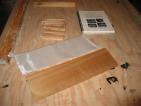
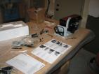
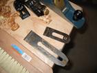
For the bevel blocks, I did the following.
- I cut all the remaining blocks out of the bevel, each 4" by 2
1/2". I botched one because I cut to aggressively at the end of the
cut, and ripped out the wood. That one was put to use as my test-bed
for testing hole sizes.
- I bevelled in the sides on all the blocks, 7° on the sides
and tall edge, and 12° on the short edge. 12° seemed to look
a bit better than 7°, 7 just wasn't enough. I also shortened the
blocks down from 4" a bit so that a clam cleat fit with maybe 1mm
extra on the top and bottom.
- I sanded the vertical corners to round them down a bit. A
block is best for this, the ROS is too big and unwieldy for it.
- I marked the spot where the holes should be drilled, by
putting the clam cleat on each block and marking the centre of the
mounting holes. Two cleats per block. Each hole should be 3/8" in
from the edge, this is the radius of the tee-nuts.
- Pound a starting mark with a nail, then drill all the holes
with a 5/16" bit. This is slightly wider than necessary, but it makes
the bolt threads go through cleanly. When they're drilled, clean up
the glass side hole with a triangle or circle file. The only trick
here is to make sure that for the bottom holes, you drill at vertical,
but with a very slight angle back, so the hole is maybe 5° off
vertical towards the narrow edge. I did this by drilling as soon as
the "level" light on the drill went on. This makes sure there is
enough room for tee-nut on the bottom edge.
- Grease the threads on all the stainless steel tee-nuts, and
then drill out a slightly larger (3/8") hole for the shaft of the
tee-nut.
- Cover the bottom holes with tape, putting the tape on the side
if the drill ripped out any wood on the bottom edge.
- Mix up some straight epoxy, then fill up the holes with a
syringe. Keep the holes full, as the wood absorbs the epoxy. Watch
the remaining epoxy in the mixing container - when it starts to get
thick or appears to kick, pull the tape off the bottom and let all the
epoxy drain out. Wipe the bottoms, and make sure there is no epoxy
"skin" covering up a hole.
- Pound the tee-nuts into the bottom, and then run a Q-tip
through them from bottom to top to clean out all the wood chips that
might be in the path of a bolt in the hole.
Epoxy Rash
posted 2004 Feb 28
I managed to get a small dollop of uncured epoxy on my forearm by
my wrist, and because I was right in the thick of epoxying stuff I
didn't clean it off immediately. Big Mistake. I can safely say that
when the MSDS sheets say
"May cause moderate irritation to the skin such as redness and
itching" they weren't kidding. I've had a small poison-ivy like rash
at the spot for a week now, and it itches. If I knew
then what I know now, I would have stopped immediately and cleaned the
epoxy off.
• • •
When I cut the cloth for the transom, I cut the 50" wide s-glass
into three strips (like the Netherlands flag) - one
each for either side of the transom, and a strip left over which I
just hung onto, figuring it would be useful at some point.
And how - all these little pieces need more little pieces of
glass to go over them, and that strip has proved very useful.
On Corrosion
posted 2004 Feb 26
I went down to the local Home Depot to pick up tee-nuts to embed in
the bottom of the centre rail/vang pedestal, as well as the bevel
blocks I just built, and while talking to the guy about thread counts
(he suggested 10/24, which Bram later confirmed),
he suggested using stainless steel for the bolts. Reduces rust. I
knew that different metals would cause problems with corrosion, and
all they had were zinc tee-nuts, so I started to wonder how to fix
this problem. Could I drill a slightly larger hole and embed a SS nut
& washer?
So, I joined a Sailnet
mailing list for Puget Sound sailers, and asked there. I got a few
good responses:
Ken Fischer (ksfischer@mac.com) suggested
Were it me, I might well go with your idea of using SS nuts and washers.
Try cutting a hole in a piece of wood of similar thickness to the
nut and washer. The diameter of the hole should be a bit larger than
the washer.
Put a piece of tape across the back side of the wood. Superglue
the nut and washer together and then stick them down to the tape,
inside the hole. Use a dab of tape to cover the top of the nut, as
well.
Mix some epoxy and use a brush to just wet the wood inside the
hole, and the surfaces of the nut/washer, which you would have cleaned
with acetone. Then add cotton flox to the epoxy until it is a thick,
but wet paste. Use that to fill in the area, essentially making an
epoxy casting.
When cured, peel the tape and you should have a pretty good nut that
can be glued to the back side of just about anything, with no worries
of the nut falling or breaking off.
Duncan Forbes (duncan.forbes@ints.com) suggested
Now onto your problem, I don't think zinc plated nuts would be a terribly
good choice. I would think stainless would be the way to go. Where have you
looked for T-Nuts? I popped out onto the internet and did a quick search and
found a couple of on-line sources for stainless T-nuts. However not knowing
the size you need I couldn't find an exact match. I used a google search for
the keywords "stainless steel t-nut".
Here is one promising link though: stainless
tee-nuts.
Another writer suggested that anything I could describe I could
find at mcmaster.com, which
after a bit of searching does indeed seem to be the case...
I also took a book out of the library: "Metal corrosion in boats:
the prevention of metal corrosion in hulls, engines, rigging, and
fitting", by Nigel Warren (Dobbs Ferry, NY: Sheridan House, 1998).
This was way overkill for my purposes, but it did have some nice
pictures of how nasty corrosion is, and you don't need two different
kinds of metals...
Here is more information I collected.
Catching up
posted 2004 Feb 25
This week has mostly been devoted to completing all the little
things that I haven't done in previous steps. i.e.:
- I cut the vang pedestal in half with my trusty razor saw (have
I mentioned how much I like this saw?), and bevelled the straight side
to 10° inwards to match up with the centre rail.
- I cut the breather holes (but not the drain holes) in station
6. I used the old station 6 to place the locations of the small 2
1/4" holes, and then measured out the positions for the 3 1/2" holes -
being very careful to ensure they were at least 4" apart. The drain
holes I'll drill later when I can ensure that they match up well with
the centreboard trunk.
- I laid down the carbon tape on side two of station 6 (side one
I did while I was applying hybrid to the board). Scraped it up with
40-grit on the sander, then used a brush to apply the epoxy to two
pieces of overlapping 1 1/2" carbon tape. Applied a second coat of
epoxy when the first was tack-free. [Update
2004 Mar 15: It may have been a good idea to put peel-ply and
plastic down on top of this (and then perhaps a layer of thin foam, so
the epoxy doesn't just migrate to beside the tape), then a board, and
clamp it down. This would have reduced the total epoxy used, and
would have made things a lot smoother and flatter. Next time, I
guess.] [Update 2004 Mar 22: I think
also it might be a good idea to vacuum bag both the bulkheads, just to
reduce the total amount of epoxy in the hybrid. Greg talks about this
here.]
- Put a 25° bevel on the bottom ends of the T-soldiers,
using the disc sander and the angle guide, then used extra epoxy from
the carbon tape to seal the exposed edge of the bevel.
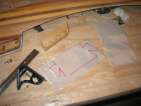
- Cut a piece of scrap bulkhead hybrid, 6" wide, to use as the
backing block for the gudgeon which goes on the transom. I traced
around my hardboard pattern to get the right shape.
- Cut and bonded the backing block for the transom bar to the
backside of the transom. Take a piece of solid cedar, 12" long by 2"
wide by 1" thick, bevel the back edge to 45° picture. Cut in half, and
bevel the inner edge to match the transom 'step' edge (about 20°).
Once that's done, bond the piece to the back of the transom. I inset
mine about 1/8" so there's a bit of extra to sand down when the deck
is installed, and it makes it a bit less messy because the epoxy can
collect in the 1/8" lip. I used epoxy/206/406 and a bit of s-glass
for the bond - in retrospect the 2" e-glass tape would have worked
better because the edge is finished on the tape, and strands of glass
wouldn't be pulling out and it's exactly the right width. The block
wants to slide all over when you apply pressure, and the glass wants
to slide out, so be careful.
Building the centre rail
posted 2004 Feb 22
I've been doing the construction of these parts a bit out of order
- since I built the strips for the centre rail, I figured I would lay
those up and do the work for them, while I was completing other
parts. At this point the book starts building the centreboard trunk
and mast step.
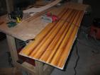
So, I layed up the centre rail - epoxy/206/406 together and 2"
e-glass tape every other layer, three strips wide and 6 strips
high. (I had previously built the 3 wide strips.) I used nails
hammered into my trusty workbench to ensure that the pieces didn't
slip out sideways - this worked pretty well, cheap, easy, and didn't
involve clamping, which would have been hard. Even with my experience
with the transom bar, I still had a couple voids, and I had even taken
a couple strips off and re-applied extra filler to ensure that
everything was nice and full. I guess excess is the order of the day.
I weighed down the layup with paint tins and glue - just make sure
they are applying even pressure side-to-side.
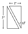
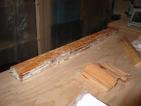
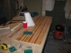
While the rail was curing, I worked on the bevel blocks. For
these, you take a 5/4" by 6" piece of solid cedar, and cut it 16" long
by 5" wide. Then split it on a bevel of 12°. This completely
confused me (although in retrospect I'm not sure why...) - the split
should look like this:
12° is (basically) the exact angle that cuts the piece in half
along a diagonal between opposite corners, when looking at the piece
end-on.
Well, I had a piece of 2x6 solid cedar, and I choose to interpret
5/4 as 1" (Bram indicates this is about right here
although it depends a lot on who you ask - 5/4 is a rough lumber
dimension, and when it gets surfaced it changes). I tried taking a
bit of the height off with my jack plane, but it would have taken
forever. And then how to cut something on a 12° angle?
The woodworking alias came to the rescue - someone assisted in
planing it down, and ran it through his table saw for me. I think
this is the only spot where I've really needed one.
That accomplished, I took one of the bevelled pieces and, along the
bevelled side, stacked the following:
- a thin layer of epoxy/206/403 on, to seal the wood
- a layer of e-glass
- another layer of epoxy/206/403. Note that I'm using 403 here
instead of 406 - it seems like a better choice for this usage
(laminating instead of bonding).
- a layer of strips, cut to 5" long, with the 206/403 mixture
between strips. 5" was just barely enough to cover the length of the
bevelled edge.
- another sealer coat of epoxy/403, this time with 207 hardener
(since we're on an outside surface now).
Apply pressure and let cure overnight. All in all, pretty quick.
Once that had cured, I did the following:
- sand down the surface (pretty quick with a fresh 40-grit pad an
a random orbital sander)
- seal the bare wood surface with epoxy/207/403
- apply another layer of s-glass, and let everything soak in
- finish off with epoxy/207.
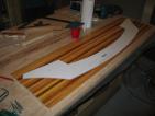
With the centre rail cured, I cleaned it up and took off all the
extra epoxy on the sides and top/bottom. I then used the disc sander
with the table adjusted to 10° to bevel both sides to the right
angle. My kingdom for a table saw - this would have taken two
minutes, and been more accurate, with one. But the sander worked out
pretty well, as long as you're careful. I also bevelled the last six
inches of the end of the centre rail - so it tapers down from the top
to 1/8" from the bottom.
Oh, and I also bonded the rudder gudgeon to the transom bar,
cleaned up a little extra s-glass which was sticking out (using duct
tape to protect the bar), and added a fillet of epoxy/207/406 to the
edge.
[Update 2007 Feb 3: There was a
question on the list
about the dimentions of the centre rail; Bram's rail is 1 3/4”
at the bottom and 1 1/4” at the top. Mine is a bit wider
— 2 1/4” at the bottom, 1 1/2” at the top.]
Building the transom bar
posted 2004 Feb 18
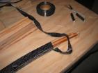
I wrapped the transom bar in graphite tape, and then 2" e-glass
tape. Before doing this, however, I coated the edges in epoxy with
406, in an attempt to fill in some of the cracks there. I'm not sure
this was completely successful, but it did help in one way. When I
came back to put the carbon tape on, the epoxy was still fairly tacky
- which meant that I could wrap the tape around, and then press it in
to the tacky epoxy and have it stick, so it wouldn't fly off again.
This helped a bunch.
With the carbon tape on, I first coated it in epoxy/207, and then
wrapped the 2" fibreglass tape around (with the edges running in the
opposite direction to the carbon tape). I then coated the entire
thing in a mixture of epoxy/207/406/graphite powder. Later, I came
back, sanded down the bar to take off some of the high edges where the
tape overlapped, and put down another layer of epoxy/207/406/graphite.
I probably should have used 403 or 405 for this application, since
from Gudgeon's handy
dandy chart it would have been less dense and more suitable to the
goal of mostly fairing with some strength.
Bram posted weights of some of the parts. Here's his list, and my
weights as well:
| Part | Target Weight (g) | My Weight (g) |
|---|
| Station 6 after holes | 1005 | 1233 (old station 6, tape on one side)
1430 (new station 6, tape both sides, no bottom drainage holes) |
| Station 8, both halves | 934 | 1195 |
| Toe rails | 1012 ea | ? |
| bevel block for sheaves | 58 ea | ? |
| Cleat bevel for clam with T-nuts | 72 ea | ? |
| Partial bulkheads, all 3 sets | 902 | 1130 |
| All 8 soldiers | 338 | 1160 (!) |
| Transom bar | 900 | 1160 (rough-cut) |
| centre rail w/ T-nuts and vang pedestal | 525 | ? |
I'm not really sure why I'm over so much: it seems like this is a
lot, especially to chalk up to just extra epoxy on the bulkheads or
something. Maybe I've got extra-heavy cedar? Maybe someone's scale
is wrong?
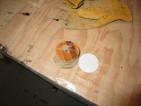
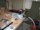
Turning the vang pedestal
posted 2004 Feb 12
I set to work on building the vang pedestal. To do this, you take
the bonded 3 1/4" discs, clean out the centre hole with a 1/4" drill
to get rid of the excess epoxy, and then put a bolt through the stack
of discs. I used a couple fender washers to protect the surface of
the discs; I used a bolt which was too long and added extra washers to
make sure I had as much thread left over as possible when the
tightening nut was on. Tighten up the nut tight, and then take the
thread-end of this and put it in your drill. Really secure this in
tightly - if you don't, it's going to come spinning out of your drill
(experience talking here).
Turn on the belt sander, and fire up the drill, and start taking
the side off. This works pretty well, but the discs have a tendency
to bounce off the sanding belt, so you wind up with a
not-quite-circular assembly. Press hard against the belt to reduce
this. The bolt threads will start to unscrew out of the drill, if you
see threads stop and put the bolt further into the drill (and tighten
harder).
Initially you just want to get the entire edge smooth. This
requires keeping the drill horizontal to the belt surface. Once the
entire edge is smooth, you can start shaping it into the right curve.
I found I had to press the top half of the cylinder into the end of
the belt at 45° to get the right shape - flared out at the bottom,
and a slight flair at the top.
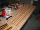
• • •
Started building the transom bar yesterday. I took the 2x6
generously cut by a friend of mine on his bandsaw, and put duct tape
over the curved edge. [Update 2004 Mar
10: when cutting pieces for the centreboard trunk, I broke a blade
and put a new one in which was a lot longer and thicker than the thin,
curve-cutting ones I was using. I realized that I could probably have
cut this 2x6 with the jigsaw with this longer blade.] I cut 14
strips, 6x55" long, 4x56" long, and 4x57" long. I put epoxy/406
(cream) in the cove of a 55" strip, laid it down on the duct tape, and
clamped it down, and then put another strip alongside it, squeezing
some of the epoxy out. Cover that entire surface in epoxy/406, add 2"
tape, more epoxy/406, and then put another two strips down. Keep on
going until you have a stack 7 high.
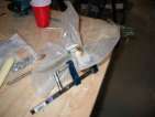
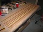
The hardest part of this entire thing is keeping things clamped
down while you add more strips on. The strips want to escape
(obviously) - I suppose I could steam them or heat them, and this
would reduce that springiness (although it would make the epoxy more
fluid and harder to control, it would set up much quicker). Keeping
C-clamps on the end is hard, because they want to slide off the ends -
I think the trick here would be to cut a notch in the bottom edge of
the 2x6 so that there is a spot for the clamp to hang on to that's
relatively parallel to the angle of the strips at the end.
I think in retrospect I would build the bar this way:
- Cut three 4" by 12" strips of plastic.
- Cut the strips: 4x 55", 4x 56", 4x 57", 2x 58". Cut the 2"
tape as well, 1x 55", 2x 56", 2x 57", 1x 58".
- On your workbench, lay up the strips two wide, seven high,
with 2" tape between each layer. Use epoxy/205/406 (heavy cream).
You may need to use 206 to slow down the curing a bit.
- Once everything is laid up, wrap the plastic around the
layup at the 1/4, 1/2, and 3/4 points. Put spring clamps vertically
at these points to stop the strips from sliding sideways.
- Take the layup, and put one end against the jig. Clamp
and/or tape that end to the jig. Then bend the entire layup over the
jig, and clamp the middle. Bend the other end down, and clamp/tape
the end.
It might also have been a good idea to have the template laying
on it's side on the workbench, rather than having the bottom edge on
the bench. This way it would be easier to clamp and the strips
wouldn't be able to slide out as easily.
I'm not sure how it would bend, but it seems like it would be a
lot easier than fighting with individual strips that are springing
loose when you release a clamp to try and get a new strip down. The
layup is slippery, so it's hard for the clamps to get a grip, it's
hard to get the epoxy under the tape where the clamps are holding,
tightening the C-clamps causes the strips to get twisted and slip
sideways, and when you add a new strip all the previous strips pull the
tape out and you have to fight to get it back in place.
I also discovered (the hard way) you need to clamp the middle,
otherwise the layup won't get a good solid bond, and there will be air
holes in the middle - you can't see this while you're working either
because there's just a big mess of epoxy and tape.
[Update 2005 Aug 15: there was a conversation
about how to build the jig for the transom bar, including a picture
of Rob's jig. He cut the 2x10 into two pieces (in a long arc) and
then clamped them together with the strips in the middle. This is an
even better idea - no voids, no wrangling with bits of plastic, no
problems with individual air pockets.]
Cutting the transom
posted 2004 Feb 08
I cut the transom. This was just like cutting the bulkheads or
the stations - line everything up, making sure the strips are exactly
parallel to the waterline, put the pattern paper side down, and trace
around it with a marker for the rough-cut line. Then cut it out with
the jigsaw, and then route around the pattern. I've found that doing
this rough-cut step makes taking off the excess with the router much
easier, especially if there isn't a lot of excess to remove. I
managed to avoid destroying the template for the station this time too
(!).
Next up was completing the centre control block bevels. The
bevel for these starts from 1/4" up from the bottom, and is 23°
off horizontal (i.e. 67° off vertical). The feed table for the
belt/disc only go to 45° - some other method is required.
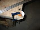
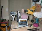
Here's what I did. First, I put the table so it was set up for
the belt, and adjusted it to 23°. Then, I clamped a straight-edge
along it that I knew wouldn't flex much, and adjusted the belt so that
it's base was parallel to the straight-edge (picture). Thus I know the
belt is exactly 23° off horizontal.
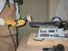
The table is too far from the belt to be able to feed material
into it, so I needed to create a platform to feed things in. I dug up
a scrap piece of 2x6 (the end of the transom jig 2x6) and first used
the table to sand down the end, and then took my pull saw and cut off
an additional piece parallel to the sanded edge. I drilled two holes
on the table, and two on the wood, and bolted the wood to table (see
here).
Feed in the block, and when there's about 1mm remaining at the
closest point, stop and move to another side. The belt is good for
starting, but not finishing. The belt curves up on the sides, and so
it's better to finish with the disc sander, as it is perfectly flat.
And since the angle formed by the two edges is 45°, you can use
the normal feed table.
For the disc, you have to be careful that the right side of the
disc (which is moving upwards) won't rip the piece from your hands and
give a weird angle. I found that if I gradually moved the block
closer a small amount (1mm), then press the bottom edge onto the table
(thus pushing the top edge into the disc), I could reduce the
likelihood that the block would "jump" and pull off some weird angle.
I also cut out six 3 1/4" pieces from the scrap transom and
bulkhead material for the vang pedestal. I roughed up the sides with
the random orbital sander, then used epoxy/205/406 to bond them
together (no need for extra glass). I put a 1/4" bolt through the
centre hole while I was getting everything together, then removed it once I had the
clamps on.
Continuing the transom
posted 2004 Feb 05
Did a few things this week.
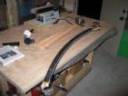
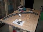
First, I scribed out the 72" arc required for the transom bar jig
on a piece of 2x6. The board is a bit too wide for me to cut with my
trusty jigsaw, a handsaw won't cut it, cutting a curve like that with
a circular saw won't work. And so a friend is going to cut this out
on a bandsaw, the ideal tool for the task.
I took the pieces I bonded together for the rudder gudgeons and
used my (newly assembled) belt/disc sander to take off all the extra
epoxy and glass. This flew by - that belt sander can really remove
material. I then set the table up for the 45° angle on the ends,
sanded that off, and the 12° angle on the sides - absolutely no
problem. Making this part was pretty fun.
I bonded the 4-strip wide pieces of the centre control block
bevels together. This is the same as the rudder gudgeons - epoxy/406,
leftover s-glass between the layers, and clamp it together. Be sure
to protect the top and bottom from the pressure of the clamps - I used
a couple small sheets of plywood this time. Also, have clamps
clamping all three axis (I didn't do one, the one with the length of
the strips). The strips will slide out in the direction you don't
clamp otherwise. My strips were cut at fairly tight tolerances, and I
got lucky they didn't move so much that I had to rebuild the piece.
I had some extra epoxy/406, so I decided to cut and glue together
the 32" strips needed for the centre rail. This time I used epoxy
rather than carpenter's glue. Compared to glue, epoxy is hard - when
I came back later and knocked off the excess resin, the epoxy takes
quite a beating...
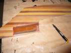
Next up was the backing block for the transom bar. This is built
from a scrap piece of dimensional cedar. Since I bought all mine, I
made a trip out to Dunn Lumber
and picked up a 16 foot long piece of 2x6, with nice tight end grain -
expensive, but ideal for what I need (I'm not sure how people build
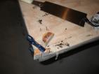
cedar decks, it has to cost a fortune). I used my newly acquired
circular saw to cut a 45° cut with the grain in from the end, and
then a 90° cut parallel one inch further in. (You can see the
lines here.) I then cut
off the piece, and put it on the belt sander to take it from 1 1/2"
thick down to 1" thick. A planer would have been handy here, alas.
I scraped, planed and sanded the second side of the transom
material. There is a slight bow away from the already glassed side of
the transom - I'm not sure exactly why. Perhaps the temperature
changed slightly, or the humidity, or perhaps even the glue
between the strips tightened up and pulled together a bit. It's not
terribly noticeable, so I'm not too worried about it. If I had hit the
second side with the sealer coat sooner, it probably wouldn't have
happened. (Note to self: be careful leaving the hull unstapled...)
Like the outside edge, I laid down a sealer coat of epoxy/406,
with 205 hardener. Once that had reached almost tack free about 8
hours later, I sanded it down a bit to provide rough surface, and laid
out the satin s-glass. I worked this in quite a bit this time - the
sealer coat was still a bit tacky, and so the glass stuck to it.
Getting all the air bubbles out is worth the time, however, they are
easy to see when you're done (as I found out from the first side). It
will probably be worth it to go over the entire exterior hull and
putty all the staple holes, just to eliminate the bubbles - they are
really easy to get, otherwise. Saturating the glass took about 9
squirts of epoxy, and I probably pulled 3 off to get it to "wet, not
shiny".
Because it's cold, I've been heating the epoxy resin in front of
the space heater before mixing it with the hardener. This makes a
difference - the epoxy cures faster, and it's easier to work in
(because it's less viscous). I almost didn't catch the "tack free"
stage after applying the glass because it cured so much faster.
[Update 2005 Jul 28: it may have been
better to use hybrid on the back side of the transom, for increased
strength. Greg suggests that here.]
Building the little bits (2)
posted 2004 Feb 01
Next up is preparing the outside surface of the transom. I
scraped off as much glue as I could (without seriously damaging the
strips), then planed it flat with my jack plane. Next up was using my
new Makita random orbital sander - this sucker *rocks* and works much
much better than the DeWalt sander did.
With the transom piece sanded flat, I mixed a sealer coat of
epoxy up. Because it's an outside face, this needed 207 "Special
Coating" hardener. To improve the stiffness, I also added a little
406. 207 gives the epoxy a yellow tint, which I don't like as much as
the plain colour, but given that it also makes the surface much less
prone to UV damage, I'll live with it. ;-)
While that was curing, I used a paintbrush to coat the second
side of the small pieces with epoxy/205. I then moved on to putting
2" e-glass tape along the bottom edges of the T-soldiers. This is
simple - straight epoxy, just saturate the fabric and bond it right
on. This would have been a good spot to use peel-ply - this way a
bunch of the excess resin could be forced out, while ensuring that the
slight overhang of the tape over the edges of the strips could be
wrapped around the strips, keeping the tape tight to the strips.
Peel ply is a fabric-type release
material used in vacuum bagging. It is usually teflon coated
fibreglass for high temperature molding, or nylon for room temp
work. Epoxy will wick through it (similar to wetting out glass) but
the epoxy won't stick to it. The wicking action will remove excess
resin from the layup. When the epoxy has cured, you peel the material
away from your laminate, taking the excess resin with it. You are left
with a rough-textured surface which helps when you want to bond
additional layers or parts to this first layup. (from here.)
Once the epoxy on the transom board was dry, I hit it with a
sanding block to take off some of the high spots. The particular
spots to worry about are the "ridges" that are created by drawing a
squeegee along the surface - the resulting line of epoxy that runs the
length of the draw. With those knocked, off, hit it with the vacuum
being very careful to get all the little bits of dirt, sawdust and
epoxy dust off.
Then, lay down the s-glass. The s-glass is a 2x2 satin weave,
and it's very sheer - the slightest imperfections will show through
the material. Small bits of dirt or dust will become bumps on the
surface. Use the brush to flatten it out, and be sure to take some
time to do this - it is much harder to work bubbles out of this stuff
than the hybrid.
Apply resin/207 mix. I was surprised at how little was required
for this surface - a lot less than the hybrid. I was prepared for 10
squirts, but only needed about 8. It's also important to work out the
bubbles. Using the roller, or fingers, it's often easiest to work the
bubbles to the edge of the board than to get them to "blow through"
the glass, and it's a *lot* harder to get rid of them all than it was
for the hybrid. Worth the effort though - those bubbles are weak,
unbonded spots.
While that was curing, I bonded all the boards together for the
rudder gudgeon. I used epoxy/205/406 as the glue with layers of scrap
s-glass between all the boards - board, glue, glass, glue, board
(repeat). Once this was all set up, I wrapped it in plastic and
clamped it all together to get a good solid bond between everything.
Don't forget to put a buffer block between the cedar and the clamp -
you don't want to (like I did) make a nice round dent in your cedar.
(Fortunately, I can put the dent on the side facing the transom...)
Once the transom had reached tack-free, I came back and used a 2"
paintbrush to apply a second coat of epoxy/207. I managed to loose a
bunch of bristles while doing this, and it's a hassle to fish them
out, but it would be ugly if they showed through.
Page 54 of 62
« First
…
«
52
53
54
55
56
»
…
Last »