*Still* aligning the strongback
posted 2004 Apr 27
Ever more alignment. In homage to the "man with a watch" quote, I
keep thinking of ways I could double/triple/quad check alignment and
trying them out.
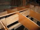
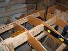
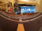
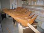
I attached strips to the edges of the gunwales. I clamped them to
the end stations, and stapled them to only a few stations, to see how
the strip touched the other stations.
From this, I wound up moving station 9 up about 1/8". Stations 3
and 5 had to be twisted a bit; the gunwales were not quite evenly
positioned on the strips. Having strips on both sides caused me to
shift stations 8 and 9 over to the other side slightly, and then twist
them a bit to ensure they fell at the same position in the thickness
of the strip on both sides. When I put a level to the centerlines,
they weren't level anymore, compared with station 10. This was a
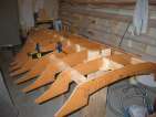
mistake - I later flipped the jig over, and sighting down the wings
found that stations 8 and 9 were twisted and causing the wings to be
unbalanced on the two sides (hole on one side, bump on the other).
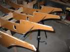
Once I had everything aligned to satisfaction, and shims holding
all the stations in the place I wanted them, I went back and screwed
wood brackets into the
side rails and then screwed the stations into them. This reduces the
twist and makes the entire assembly a bit more rigid.
With everything screwed down, I flipped the jig over and sighted
down the wings. Immediately the problem with 8 and 9 became apparent
(damn). I had to flip it back over and then re-re-adjust stations 8 and
9 back to level. (As you might imagine, there are now a lot of unused
screw-holes in the particle board of the strongbacks...) To try and
avoid this problem again, with the jig still hull side up I sighted
down the wings on the deck side and made some minor adjustments to
station 14. I also lifted
the bow up as much as I could, and fired the laser level at the
centreline on station 8. I then lined up the laser so it also passed
through c/l on station 2, and checked all the centrelines for all the
intermediate stations. They are all pretty good - within 2 or 3mm. I
may need slight adjustments, but not much.
Aligning the strongback (again)
posted 2004 Apr 20
A man with a watch knows what time it is. A man with two
watches is never sure. - Segal's Law
With the stations out at most 1/8" to each other, I sent mail to
the list asking if this was close enough (or, how close did everyone
else get theirs)? The answer: not close enough. Greg sent me back a
long missive on how he aligned
his forms, and I read over his mail and started re-adjusting mine.
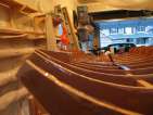
First, I flipped the hull over. If the hull is the part that needs
to be fair, then I might as well work on fairing that side.
I bought a few cheap bubble levels (making sure that on a flat
surface, they all read the same value). I levelled station 10 without
moving it, assuming it would be the reference station. Then, working
outwards, I levelled all the other stations to be perfectly level,
using the level on both sides of the centre rail. This took a while,
as I had to sand off
material from the top or bottom of the side rail hole to adjust the
position.
At the same time, I also ensured that all the stations were
perfectly centred on the centre rail. I did this by shining the laser level down the
centrelines, and moving the stations around to centre them. I
know now that the stations are out by at most the width of the laser
beam (about 2mm).
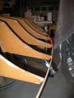
Next, I laid a strip down on the stations at the centreline, and
checked to ensure that the height of all the stations was right. A
few were out by maybe 4mm - and thus I had to raise them up so they just
touched the bottom of the strip.
I quickly checked if I could sight the laser through the holes, but
gave up. It didn't work. I'm not sure it matters either - what's
important is that the strips are fair to the strongback.
More strongback alignments
posted 2004 Apr 11
I slid the side rails
into the assembly. This was pretty easy - a couple spots where they
were overly tight and I had to rasp off some excess from the station,
but otherwise they fit in smoothly. It was helpful to let them rest
on the bench as I slid them in.
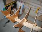
Next, I put station
1/2 on the strongback and aligned it. I did this by clamping a
carpenter's square along the waterline datum mark, and then ensuring
that the 1/2 station edge aligned with the top edge, and that the
centre of the station was as far over as the centreline of station 1.
I added an extra wood block below the 2x2 to stabilize the
station.
Now that all the stations are on the forms and relatively secure, I
began doing other things to try and verify that they are all in good
alignment.
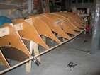
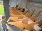
First, I sighted down the forms. It's surprising how effective
this is - you can pretty easily see when a station form is twisted and
needs adjustment. The thing to be careful of is parallax error - it's
also easy to be tricked if you don't line up a couple reference points
and ensure that the station you're adjusting is out relative to those
points. Sighting also doesn't help any with ensuring that the
strongback assembly isn't twisted. Sighting resulted in making a
slight adjustment to station
11, it needed a bit of a twist.
Next, I clamped strips
along the waterlines of the stern 6 stations, and put a strip along
the clamped stations. This told me that they were out relative to
each other by at most 1/8".
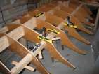
Finally, I took the cove
off a dozen strips in preparation for building the side rails. I
screwed two pieces of plywood into my bench, and then clamped the
strips to the plywood and ran the plane over them. It's sure nice
having a benchtop that I can ding up a bit.
Assembling the strongback
posted 2004 Apr 08
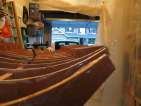
Once all the preliminaries were complete, I started the task of
actually aligning all the stations on the strongback. This is fairly
tricky. I started by shooting the laser level through the holes I had
drilled in the station forms, and then moving them up or down slightly
to get the laser through more holes. As I worked, I shimmed the
centre rail to keep the form from twisting back to it's original
position.
This worked out ok, but one problem is that it's difficult to tell
if the form I'm working with is out of alignment, or if the adjacent
forms are. The way I got around this was to put a steel dowel (piano wire)
through the extra set of holes in the form (I drilled two sets, one
closer to the c/l, one further out). This made things much easier,
because the stations would then move more as a group.
Once I had the laser sighting through all the stations, I knew that
the stations were out by less than 3/16" to each other. I then went
back and screwed them all down with at least two screws to stop them
from twisting. Note that it's important to clamp the station to the
blocks on the rail, otherwise the form will pull away from the block
when the screw goes in.
Next, I put the 2x2 in the bow forms. This didn't take much work -
only a couple forms required any additional rasping.
Information from the list
posted 2004 Apr 07
Station 6 really is cursed. After building two of
them, Bram clarified that the carbon tape should
only be applied to one side. I did both. Drag. I know that
second side added about 200g to the weight, but I'm not going back and
building another one...
A few other documents which have been posted:
- If you align everything with the hull up (as you should, since
that's the side that has to be fair) then you may have to bump
stations 11 and 12 up 1/8" when you flip the strongback over to build
the deck. (mail)
- The rudder cross section (mail)
- The rudder plan
- Details of the centreboard (mail)
- A small java application to create
NACA foil sections, and dump them into a spreadsheet (mail)
- Three coats of graphite on the bottom, be sure to mix the right
ratio all three times, and don't varnish the graphite (mail)
- The AMP is the aft face of the station 14 template which
technically is also station 14. (mail)
- Move the launcher throat back three inches (mail)
- How to make your own
launcher throat (from the website)
Preliminaries to assembling the strongback
posted 2004 Apr 04
With the rails built, the sawhorses assembled, and the holes cut
from the strongback templates, it was time to actually start putting
the strongback together.
- I started by sliding all the templates on to the rail, to ensure
the holes would slide over the rail everywhere.
- I took all the templates off, and measured exactly where
all the stations should be positioned. I then drew lines around the
top and both sides
showing how the station should line up.
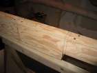
- I cut a small thin line 1/4" into the end of the rail, in the
middle of the rail, on both ends. I put a string through this divit
on both ends and drew it tight. This makes sure I have a perfectly
straight line along the entire length of the rail, and as it happens
the rail bows by around 1/8" to almost 3/16". Draw marks where the
string intersects the lines drawn in step 2.
- Do the same thing with the string on the side, 1 1/2" down from
the top edge. It's helpful to do this on both sides (I didn't, and
wound up having to try and transfer the marks to the other side). If
you have marks on both sides, you have some indication if the station
is twisted (by looking at how the c/l intersects these marks). My
rail is so bent that I used
the laser level to ensure that the string was actually straight.
- Now it's time to screw blocks onto the rail. I used the system
from Kayak which differs from Bram's - Kayak uses two
small pieces, at 90° to each other. Bram uses 11 1/2" long pieces
of ply to ensure things are vertical. The nice thing about the Kayak
system is you can ensure the station is 90° to the centerline.
Start by clamping a
carpenter's square to the side of the rail, lined up with the
string marks made on the side. Pull the station flush, then screw the
vertical block on the other side, also flush with the
station.
- Repeat the process with the horizontal block.
- Then repeat for every station, except station 1 and 14 (which
are screwed on to the end of the rail).
While I was screwing these blocks in, I also spent some time trying
to align the frames with each other by shooting the laser through the
holes I drilled. This was mostly to determine if I wanted to rasp off
more material from the inside of the holes, so I could get things into
alignment. This is folly. It's better to get all the stations on,
and then align them all at once, than to align them as you go.
Once things are aligned, I used shims to keep them
in place. I bought a package of the furniture shims, and then just cut off 1/2" chunks - that
way I would have a number of different width shim pieces.
Safety notes: A couple important safety notes. First, while
screwing one of the drywall screws into the strongback with my power
screwdriver, the bit broke. And it broke in such a fashion that the
piece flew backwards and hit the front of my ear. To that point I had
thought "driving screws, why bother with eye protection?" Well, there
you have it. (I also went out and bought some high quality driver
bits instead of the picked-out-of-cheap-collections bits I was using.
I had actually commented to Tamara "the pieces in this kit are so low
quality I'm not sure when I would ever care so little about the hole
I'm drillijng to use them." Guess that includes driving the screws as
well.)
Second, I was sanding one of the shims down to the right width, and
didn't bother do hook up the vacuum. The shim (small to begin with)
got stuck between the disc and the table, but when it did this there
was a loud "bam!" as it popped in there. I thought the circling
sawdust had started a flash fire - but there was no smoke or smell.
None-the-less, I'm using the vacuum now.
Page 52 of 62
« First
…
«
50
51
52
53
54
»
…
Last »