Stripping the deck
posted 2004 Dec 31
Now that the hull is complete and hung, it's time to work on the
deck. I flipped the strongback over, and started by making sure
everything was aligned. The list
had said that stations 11 and 12 might need to be bumped up slightly
to ensure everything was fair. In my case, I had to do a couple other
adjustments - station 11 up around 1/8", station 7 down 1/8", and
shims (one or two layers of Cheerios box) on a number of other
stations. The biggest shim was on station 3, probably to match
the shim I put on station
5 on the hull. I determined all this by laying a strip down the
middle, and then checking to see if the strip touched or needed to be
pushed to touch the station.
With things aligned yet again, I used my new bandsaw with my custom fence to cut my
accent strips. These strips are regular 3/4" yellow cedar, but I
decided to cut them slightly narrower for a bit of flair. My dad
acted as an infeed, pushing the strips against the fence, and I pulled
them through, and generally we got quite straight cuts (which you
might not expect from a bandsaw). It wasn't perfect, but it was
pretty good.
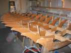
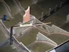
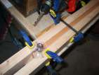
I then cut the bevel on the first two strips, numbered everything so I
would know the right order to install them, and stapled down the
centre strip. This one has to be perfectly straight since
otherwise all the other strips are going to curve around with it. For
all these centre strips, I taped them to each other to
be sure I had good contact - I want to avoid glue lines if possible on
the deck.
With all the sighting to get strips straight, I found that some
stations didn't seem to be perfectly fair. I wound up going back and
pulling the staples for a few stations, and installing shims
underneath. I did this at stations 8 (1 layer), 9 (2 layers) and 11
(1 layer). Two layers adds about 1/8". These are small adjustments,
but they seem to have improved the lay of the strips - anything more
seems pretty minor. It's frustrating to have to make these adjustments
now, after spending all that time truing the hull side of the
strongback...
I had been worried about how many strips go in the centre, but it
turns out that's not really a problem. Once the strips start to curve
up the sides (and need
screws to keep them in place) you know it's time to install the side strips. I stapled it
at station 7 first, then worked my way to the stern (with it hard up
against the wing step). I then bent it in place to the top edge of
station 2, made sure it looked fair all the way along, and stapled it
down from station 2 back to station 6.
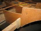
Next up was the jumper
strip which jumps from the outer strips to the centre strips.
This one doesn't fit quite perfectly, it doesn't leave a nice flat,
fair surface after it's in place - but it's going to be covered with
fairing filler anyway. After that piece, it's pretty much just
installing strips as on the hull.
Hanging the hull
posted 2004 Dec 12
Well, I've finally managed to get the car back in the garage, after
ten long weeks of being
parked outside. Max was staying over for the week, so with an
assistant to help out, I was highly motivated to ensure the hull was
hung and the jig was flipped over so I could start on the deck.
My design was largely based on the Harken Hoister installation instructions, but beefed
up to support more weight. The components could probably handle 300
lbs; the trusses should be able to support that as well.
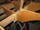
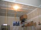
First was installing the trusses. I used 3" long 1/4" lag screws
to screw the 2x4s on to the truss - for each pulley, four
screws. (Remember that the trusses in this house are not 2x4s.) The pulleys are
1/4" eye bolts with the tail of the eye cut off (so the pulley would
fit on), then bolted to the other side with a fender washer and two
cross-tightened nuts. I centered the pulleys between the ceiling
joists to evenly distribute the weight.
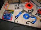
With the trusses and pulleys in place, I installed the rope and webbing. The webbing has
hooks on the ends - I tried to saw them off with my hacksaw, but
couldn't make a dent in them. I guess there really is a difference
between different steel manufacturing methods. The webbing is tied on
with a figure eight knot - tie a figure 8 in the rope, then take the
tail and put it through the webbing loop, then make the tail follow
the trail of the figure 8 again.
Next up was the wall
2x4 screwed into a top support. It shouldn't be screwed into a
stud - rather it should go into a horizontal support that runs all
along the wall. That eye bolt is pretty beefy - but can only support
400lbs of weight. I then installed the winch at the bottom, and now
things are ready to hang. I threaded the triple blocks and the hoist is
ready.
The hardest part of all this was figuring out how to replace the
centre pulley system on the original hoister. My original idea was to
use two large Home Depot pulleys attached by a quicklink, and have all
four lines go through the pulleys. This didn't work - the pulleys
weighed too much and didn't run. So I picked up two blocks attached by
a ring, and only put the line on the front through the pulleys (there
isn't enough room for all four). The ring won't fit through the metal
pipe-holder. It would have been better if it was hanging from it -
better clearance for the line. Maybe an eye-bolt would have worked
here? (With an eye bolt it could be twisted for the right
alignment...)
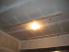
And, with all that complete, we have a hoisted boat! Now I just
have to find a place for the cradle. It weighs 56.5 lbs (pretty
heavy, I have to admit). I considered hanging it too (it will fit
over the garage door, I'm pretty sure), but at the moment I'm tired of
figuring out how to hang stuff from the ceiling. So I just put it behind the workbench.
All told, this hoist cost me about $270, compared to the Harken
Hoister cost of $200. My solution will hoist an additional 100 lbs at
least. Of that $270, $32 was on the winch, and $115 on the three
Ronstan blocks I needed.
| qty | item | supplier | safe working load, lbs | breaking load, lbs |
| 2 |
Seadog stainless flush-pin D-shackle | Fisheries Supply | | 3300 |
| 100' |
1/4" poly rope | Home Depot | 95 | |
| 2 |
10' cam buckle tie down | Home Depot | 400 | 1200 |
| 1 |
Ronstan RF30302 30mm triple block | Fisheries Supply | 1100 | 2420 |
| 1 |
Ronstan RF30312 30mm triple block & becket | Fisheries Supply | 1100 | 2420 |
| 1 |
Ronstan RF30286 30mm single linked blocks | Fisheries Supply | 660 | 1650 |
| 50' |
3/16" XLS Yacht Braid (white) | Fisheries Supply | | 2200 |
| 1 |
Fulton T600 trailer winch | West Marine | 600 | |
| 4 |
1 1/2" awning pulley | Home Depot | 110 | |
| 4 |
1/4" eye bolt (to hang pulleys) | Home Depot | 90 | |
|
1/4" fender washers, 1/4" nuts | Home Depot | | |
| 1 |
1/2" eye bolt (attaches to wall) | Home Depot | 400 | |
|
1/2" fender washer | Home Depot | | |
| 18+ |
3" x 1/4" lag screws, 1/4" washers | Home Depot | | |
| 1 |
5" nylon cleat | West Marine | | |
I stress
tested the 1 1/2" awning pulleys with 1/4" eye bolt assembly (and
the 1/4" poly rope) by hanging 180 lbs on them (my weight). Nothing
broke (or even creaked), so everything seemed to be within breaking
limits.
Making the chainplate blocks
posted 2004 Dec 3
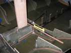
The deck plan says the centre hole for the chainplate blocks should
be 91" aft (measured from station 0 - you can use bulkhead
positions to find this location), and 29" out from centreline,
port & starboard. I put a post in the trunk and then used a
carpenter's square with a wood extension to find 29" out. Initially I
used the same 2x6 to find centre as I did to check for vertical - but
I found that the 2x6 has a slight cup, and so the square wouldn't sit
quite square on the post. This lead to a noticable (1") difference in
the position of the holes on the hull, relative to the bulkheads and
edge. I switched to a piece of solid cedar I had lying
around (which is flat) and the measurements got much more agreeable.
I also switched from a piece of strip as the extension to a piece of
metal strip - the metal is thinner and straighter. Be sure when you
do this to measure the 29" out from the actual centre - the far edge
of the post is a bit past the centre, and so an adjustment is
required.
I also wanted to ensure that the drill guides I have would drill
vertically, since I'm drilling a 1/4" hole in a 1" wide piece of
cedar. They're dead on - the drill guide has been very useful.
So, with a rough idea of where the cedar would go, I transferred the angles to
the 1" thick cedar block, and cut the piece. I then planed the bottom edge down
to the angle of the hull, and checked for fit. The
chainplates are supposed to be parallel to the edge of the hull, and
installed so they are at 90° to the deck (or slightly turned
inwards). I measured everything so they would be slighty turned
inwards, but there's a lot of play in the blocks and a slight turn
causes a lot of difference in the hole position. I cut away the top
edge so it matched up with the top edges of the gunwale, and also put
a slight inwards angle on it with the plane.
I set about cutting the second one as well. I drilled holes in the first
plate (centre hole and the two outer holes), but decided not to on the
second one. The chainplate position is a class measured position, and
I want to try and gain some additional accuracy when I fit the deck -
I'm a little concerned about the cumulative error of all the
measurements from measurements I'm making. Being out 1/4" on the
position of these holes wouldn't be good.
Page 44 of 62
« First
…
«
42
43
44
45
46
»
…
Last »