Installing partial bulkheads
posted 2004 Oct 31
This week was spent installing partial bulkheads. I've come to
think of installing this stuff as spending a bunch of time measuring,
checking, rechecking, positioning, checking some more, and then
glassing it in place.
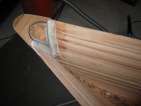
Getting the partial bulkheads in place was greatly simplified by
using the templates as a positioning device. I put the template in
place, align it all up correctly, ensure it's vertical and straight,
and then tack the actual
partial bulkheads in place with hot glue. If I don't like the
positioning, it's easy to pull the bulkhead off, cut off the dried
glue, and try again.
Before aligning everything, it's important to ensure both the hull
and the bulkheads have been sanded down so the epoxy has something to
grip. I forgot to do this a few times, it's a hassle to take
everything out and reset it.
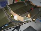
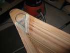
Once everything was aligned, I filleted them in place with
epoxy/405 making a nice 1/2" radius fillet (using a washer to get the
exact radius). I then covered them with 1" glass tape, and painted on
plain epoxy. I used clamps to pull the hull wing up against the
actual bulkhead - for station 7, a lot of force was required, so I
used my QuikClamp clamps
instead of the spring clamps. One bulkhead 10 popped off when I
clamped it - hot glue not quite strong enough - so I had to re-align the bulkhead.
I also began constructing the centreboard trunk. In a conversation
with Greg, he suggested the only change I might want to make to my
centreboard trunk would be to add 1/8" of width. This would be within
measurement rules tolerance, and would allow me to use a slightly
thicker board. So I decided to add some additional hybrid around the
outside of all my c/b trunk vertical pieces. (If I were to build these
vertical pieces again, I would (a) glue a strip on the edges of the
bare wood so they were 1 5/8" thick, and (b) use a long length of
hybrid and wrap it around the post five or six times. It's too fussy
to add pieces on after the fact, as I am now.) Once that was ready, I
bonded all the verticals
onto the first side of the trunk using an epoxy/403/406 mix. Inside
the mast step, I used a large, 1/2" radius fillet; inside the c/b
trunk, I used a 1/8" radius fillet. I didn't use tape - I couldn't
figure out how I would put the tape on the other side once it was in
place...
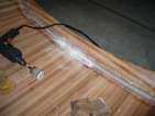
Before VMG skiffs stopped production, I had them build me a few
pieces. I picked up the vang
arm assembly and the vang
arm itself, as well as a length of peel ply. These are the more
reinforced versions - they have two layers of graphite/hybrid in them.
They are very high quality - they just need a layer of 207/graphite
and they'll be ready to go.
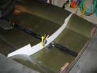
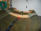
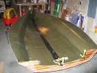
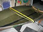
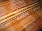
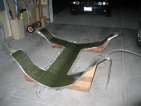
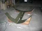
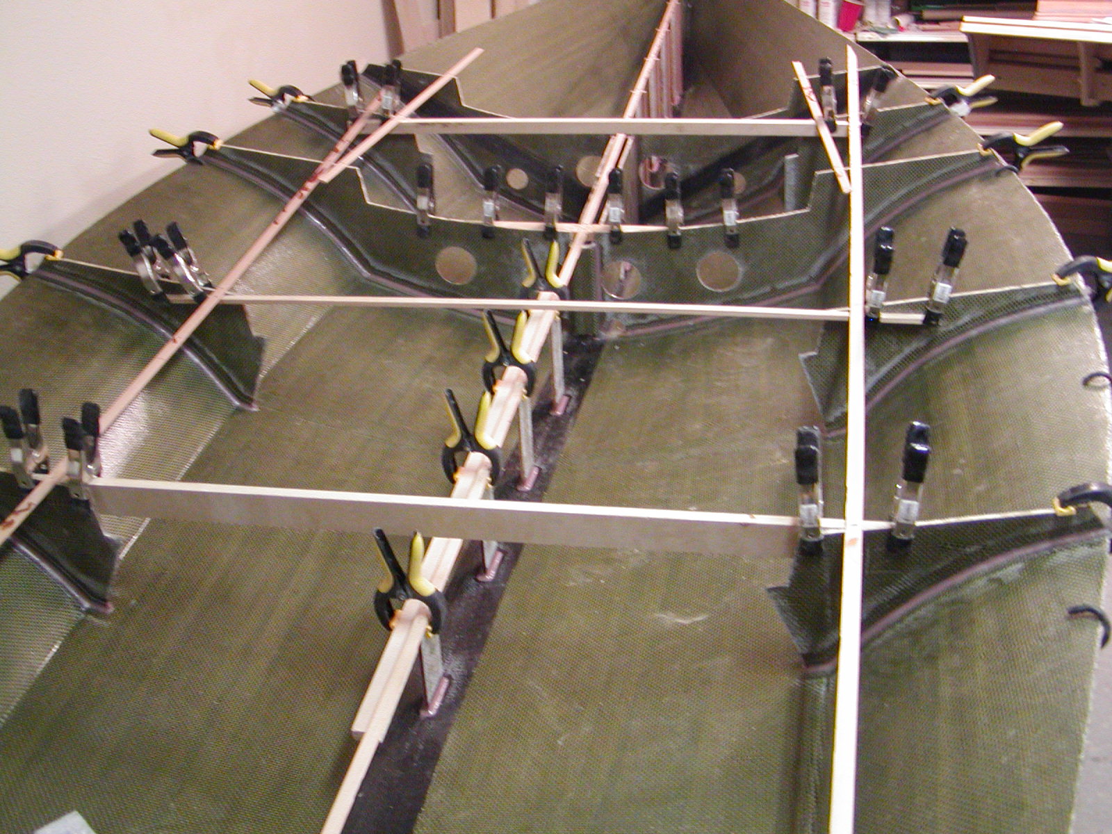
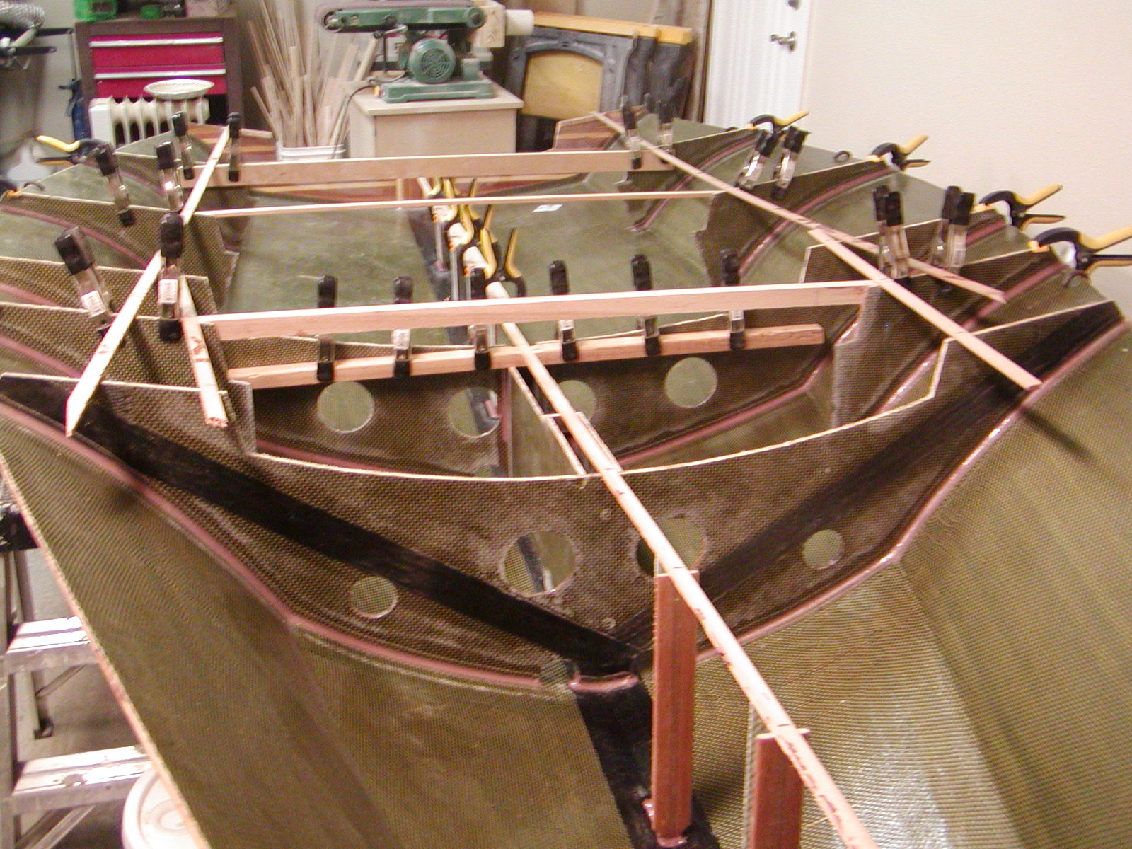
[Update 2005 Dec 7: There was a conversation
about how to best install the centreboard trunk and the partial
bulkheads. Mark used a system similar to mine, except he clamped on
2x4s onto the partial bulkheads instead of the templates. And the
strip running lengthwise along the partial bulkhead is a good idea to,
to ensure correct spacing. Picture
one,
two.
Ensuring that stations 6 and 8 aren't bowed can't hurt, but it seemed
to me that they already would be by the time they were installed.
Maybe to ensure the centreboard trunk intersects at exactly the
correct position...]
Installing bulkhead 6
posted 2004 Oct 24
There's an old saying in boatbuilding: the hardest part of
building a boat is that there's no straight lines. Oh, how true.
I spent most of the first part of the week pondering how exactly to
build the centreboard trunk. Ensuring the c/b trunk is centered,
straight, and perfectly vertical is pretty important, so I wanted to
be sure I did this correctly. Eventually I mailed
the list asking for clarification on a number of questions:
- Build the trunk as a unit, then drop it in.
- Always use tape when bonding with filets, as fillets alone
provide little strength. Don't filet the inside of the trunk (or if
you do, use small (1/8") radii fillets).
- The forward end of the trunk is bonded/filleted to station 6.
- Put the trunk in last, after all the soldiers are in place, so
you can align it up perfectly straight.
- Don't install the top/bottom blocks until after the holes
have been cut in the deck/hull. (i.e. the blocks aren't in there
when you bond the trunk to the hull.)
- The 1 1/2" x 1/2" vertical posts at the front and back of the
centreboard part of the trunk are bonded in place - they are not
attached there with 4200.
I also talked to Roger of Aquilo
Boats (in Calgary!
sails on the reservoir!),
mostly to have someone else to bounce ideas off of. He (strongly)
suggested cutting the hole in the hull now, while the trunk was not in
place - because it is very hard to cut the hole afterwards. The
problem after is that any tool you use (other than a dremel) has too
big a draft, and will hit on the lip of the centreboard trunk. Bram
checked out Roger's first c/b trunk and as a result posted this
message - directing builders to avoid point loads.
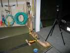
So, the first, and most important objective was to find the
centreline again. Roger suggested a laser line. I picked up one of
these and started with it on a tripod. The problem with this was that
the plane created by the laser line can intersect the points on the
transom and bowpiece, but it may not be perfectly vertical to the hull
- and thus is slightly out at the deepest point in the hull. Putting
the laser on the hull itself at least reduces (but does not eliminate)
this problem.
The next step was to establish a vertical. Since both of the edges
of the hull are trimmed evenly (within 1/8" at least), the hull should
be level across the edges. So I put a bar across both wings, with each
end equidistant from the bowpiece, and then hung a bob at the exact
middle point. As long as the rod is level, the bob will be
vertical. The laser line will light up the entire string if it is
vertical.
I added one more error reduction technique. I drilled a small
(3/32") hole through the hull from the bottom side at about station 4,
where the hull comes to a fairly sharp point. Then I kept the drill
bit in the hole, put a tape flag on it, and that is another data point
to find the centerline.
With all that, I marked the centreline.
The bob was a washer, so I put the washer on the drill bit, and I can
use the string to verify the line is straight and running to the
middle of the transom.
Roger also mentioned that many builders are using 3/4" thick posts
in the c/b trunk rather than 1/2" thick posts, and I decided to do
this as well - I rebuilt
the posts to this new width (the first attempt). To do this,
I cut the wood out of some scrap solid cedar lying around, then
painted them with epoxy and wrapped them in hybrid. I then painted the
hybrid with epoxy, and wrapped them in plastic, and put them in this
press.
Roger also mentioned that the aluminum track which is the mast step
screws through the deck and into the top of the trunk - and that he
was thinking on his new boats he was going to reinforce that area. I
decided to do so as well - I added a second layer of hybrid scrap
along the top, this one with the cedar strips at right angles to the
other piece. For further reinforcement, I will use one of the old 1/2" thick cedar posts
at the front of the entire c/b trunk assembly.
Next is to correctly align bulkhead 6. First, I used a tape to ensure the wings
were the same distance from the transom (the bulkhead is not twisted).
I used the c/b trunk
pattern to verify the bulkhead was vertical (I tried clamping
levels to both the transom and the bulkhead, but this was not accurate
enough, and it appears the transom may lean slightly outwards, by
about 1/8" - 1/4"). Finally, to reduce the gap between the bulkhead
and the hull (there shouldn't be any gap - station 6 and bulkhead 6
were cut from the same pattern), I put shims between the hull and
the cradle to force the hull into the correct shape. Once I was
satisfied, I tacked it down with the hot glue gun, and I'm ready
to bond with epoxy.
[Update 2005 Sep 12: There was a conversation
about these gaps and how to eliminate them. Christian suggested:
I think this is a common issue. Both Greg and I had this problem. The
way we fixed this was to put a strap around the hull with 2x4 blocks
with carpet or a towel. The blocks are placed inside the strap on the
places you want to push in. When you then tighten the strap it will
push in those sides. If you have a better/easier way lets hear it. The
procedure will not create problems where there are no stations. If
anything it will probably just correct it here as well. While the
strap holds the side in place you epoxy in the bulkhead.
]
After all that, the epoxy is pretty easy - epoxy/205 and 405
filleting blend, with 1" tape painted with epoxy/206. I mixed the
epoxy/206 before starting the filleting, I changed my mind about the
hardener I wanted to use for the fillets once I got started. 205
worked fine. The only trick was trying to create a good exit path for water to run
out.
The hull is certainly becoming more stiff. When I took it off the
forms, I had a helper at the bow, and me holding the transom. You
could detect a certain flexibility across both the length and the
width, as if it tried to flatten itself out a bit. With the hybrid
on, it is much more rigid and keeps it's shape much more willingly.
And with bulkhead 6 in place, the hull isn't going anywhere,
especially forward of the bulkhead.
A couple other notes:
- When building bulkhead 6 (
v1 &
v2)
it's probably worth putting a 2x4 over the glued up strips and
clamping them down to ensure the assembly is flat. I can see a
slight wave in bulkhead 6 - not enough to be bad, but
noticeable.
- I neglected to remove any material from the chine point on the
bulkhead, which I should have done (since I added a fillet in the
chine on the hull...)
Glassing the inside of the hull
posted 2004 Oct 17
With the full sealer coat applied, I sanded everything down (again)
- partly to smooth things out even further, and partly to remove some
of the excess weight of the epoxy. Epoxy is a lot harder to sand than
cedar, though, it takes a while to make much of a dent. With the
sealer coat sanded out, I went back and applied a third coat of epoxy to the
staple holes, this time mixed with 403. With some of the leftover
epoxy/403 mixture, I also put down a bead of filler along the chine line so the hybrid
wouldn't have to fit in a very sharp corner. Then sand down the final
coat, vacuum up the dust and bits, and we're ready to lay out the
hybrid.
It took about an evening to cut and prepare the hybrid. The hybrid
is 50 inches wide and should be laid out in strips running widthwise
across the hull, each strip overlapping by 2 inches. The first sheet was 86 inches
wide; the second about
the same width, the third around 45 inches. For the fourth piece, I rotated the
hybrid 90° so the finished edges of the hybrid were hanging out
the gunwales. To ensure everything correctly overlapped by 2 inches,
I drew alignment marks
and ensured they were all the same distance from the nearest station
line. This worked pretty well, except at the bow, where the longer
length of the flares caused the lines to be too far forward. I also
ensured there was a one
inch overlap with the transom.
[Update 2005 Jul 28: Greg mentioned
in a post
that putting the hybrid in on a bias might increase strength:
While it has not been recommended in "the book" it is possible to put
the hybrid cloth on a bias inside the hull so that it has most of both
kinds of the fibers traversing the joint with the transom. Cut the
hybrid on an angle at the gunwale to avoid wastage as it drapes off
the roll.
(I suspended the roll on a line running fore and aft next to the
hull when I was cutting the cloth. If you flip over or rotate (180
degrees) the next part of the hybrid off the roll it will match the
gunwale angle further up and so on, until you are complete. The
offcuts at the pointy end and or above the transom line can be used to
fill any small triangles in the back corner.)
]
As we learned in the first hybrid wet-out, hybrid
sucks up epoxy like mad. This time, a single 10-squirt cup only
covered one quarter of
the overall area of one sheet. All in all, I used 12 ten-squirt cups to wet
out the hybrid, and the second coat used another 4 ten-squirters.
When I glassed the exterior of the hull, the first coat (saturating
the glass) only took six
10-squirt cups.
However, given the areas involved, 12 ten-squirt cups to wet the
interior of the hull is a lot less epoxy than the 10 eight-squirt cups
required for the bulkhead piece. It makes me wonder how I can heat up
the epoxy so it's not as viscous when I have to wet the hybrid and
glass on the deck.
I spent a long Friday evening wetting out the hull. I started by
wetting all the hybrid, working from the stern forward. I then
applied the strips down the centre of the hull. I used three 1 1/2
inch strips, each 183 inches long (although the outer two I cut
shorter because they didn't add much going up into the bowpiece).
The instructions say to use 2 two inch pieces, so the width of mine is
only slightly wider. I painted the strips with epoxy, then went back
with a squeegee to press the tape into the hybrid and work out the
excess epoxy. Finally, I trimmed the excess hybrid at the edges of the
hull, painted epoxy/205 along the edges so they would be well
saturated, and removed the excess epoxy/205 with a squeegee.
All that wetting took a while. I started about 8pm. It took 1 1/2
hours to wet the hybrid, and 30 minutes to get everything else done.
I used epoxy/206 for everything, and the garage was at 20°C. I
expected that about four hours later I could put the second coat on,
so around 2am. I spent a couple hours checking for outgassing, then
went to bed and got up at 2am and checked if it was tack-free. Still
tacky. Back to bed. At 3am I checked again. Still tacky. Went to
bed. At 4am got up and checked again. Still tacky. Got fed up and
went to sleep until 5:30, by which time it was ready for the second
coat - 4 ten-squirt cups applied with a roller. In retrospect, I
needed to use the 206 (it would have cured too quickly otherwise), but
checking every two hours was probably enough. I didn't have much of a
problem with outgassing (all that prep paid off), but there are still
probably 5 or 6 bubble holes - not too many. They're very difficult
to find without good edge-on lighting. There are a couple spots where
the bubble has actually blown in the epoxy on top of the hybrid - a
good thing, since it wasn't trapped under the hybrid.
Cure complete, I sanded
off the edges (trimming loose hybrid strands with scissors) and
put the hull back on the
form to mark where the stations lie. The hull doesn't fit the
forms tightly anymore, so the marks are rough guidelines, but they're
better than nothing. It's important that the bulkheads are vertical,
so this is an attempt to provide some data to ensure that is the
case.
[Update 2005 Aug 28: Like the underside of the deck, at this
point I should have installed protection patches on the hull
underneath the soldiers and t-soldiers.]
Sanding and filling holes
posted 2004 Oct 10
Now that the hull is flipped over, I started to prep the entire
inside for it's layer of hybrid. Last week I scraped it down and took
a couple passes with the sander, this week I'm cleaning up some of the
other small bits.
First was installing the backing block for the rudder gudgeons. I
sanded down the tape and
filler along the back edge and then clamped the backing piece in place
with some epoxy/403.
Next, I chiselled away a cone-shaped piece of the bowpiece. This
is ostensibly to reduce weight, but really I think I did it for the
appearance. The only concern when doing this is ensuring that the
chisel doesn't pull out some of the top edge of the bowpiece, which it
is wont to do. At the beginning, be careful when pulling out the
chisel after having driven it in. Once I had roughed out the pattern
to within 1/4" of the line, I came back with my cylinder sander and
completed the edges.
Then, two or three passes with the random orbital sander &
40-grit paper. Then I filled all the staple holes
(and other obvious holes) with straight epoxy. This is to stop
bubbles, and there were plenty. I sanded all that
down, and applied a second
coat - the entire surface took two 4-squirt cups. Sand all that
down, and apply a third
coat. For the third coat, I decided to go with a complete sealer
coat - this way I seal up spots that might not seem like obvious blow
holes, I can go back and patch those blow holes again, and I won't
need to use as much epoxy when I apply the hybrid. It took 24 squirts
to cover the entire interior (in some places quite thinly). Some of
the staple holes were *still* blowing bubbles after this.
Completing the cradle
posted 2004 Oct 2
Completed the cradle (finally!). With everything attached, I
trimmed off all the drips, and then coated everything in 207/graphite.
I put on a second coat of 207/407/graphite, sanded lightly, and
finished with a third of 207/graphite. Next, I started attaching the
indoor/outdoor carpet. The stuff I have has a mesh of jute attached
to a felt like matting that actually holds the plastic carpet fibres.
So, it sucks up contact cement like water. I used a total of six cans
to cover the entire thing - the long piece required two itself. I
started out with just plain contact cement, and then found the gel
stuff, which worked a little better, it doesn't flow directly into the
matting as easily.
A couple points - don't leave the carpet outside as night falls at
this time of year, because the moisture also falls and the cement
won't get tacky. Coat the carpet first and wait a bit before coating
the cradle, so the carpet can dry out. Air everything out, this stuff
stinks and will stink up the house (I left the cradle outside the
first couple nights so it didn't get in the house).
While I was coating, I managed to find a place that sold four foot
long stainless steel rods - this was tricky to do. Alaskan Copper and
Brass in south Seattle (206 623 5800) specialises in stainless steel
(among other metals). Not cheap, but it will serve nicely as an axle
for the cradle. I picked one up and started drilling the holes with a
special jig so I could
ensure the holes were straight and centred. I drilled 5 holes in the
front cradle support, filled them with straight epoxy, screwed the rod
to the cradle with stainless screws, put a line of epoxy/406 on both
edges, and then covered the rod with a layer of 9oz glass and two
layers of 12oz glass
(since I had exhausted all my 9oz). I painted again with
epoxy/graphite, and now the cradle is ready to put the
wheels on. The wheels in this case are the wheels used for the jack
stand on boat trailers - West Marine had them.
I removed the hull from the forms (with the help of an assistant).
It's light, but fragile at this point. The very first thing I
discovered is the addition of 4" of height to the front cradle support
caused the rear of the boat to be within 1" of the ground - drag.
I started scraping, and it didn't take long to get all the glue
beads off. Next up was to flatten out the bowpiece, so it is level
with the line of the hull - the belt sander made quick work of this task.
I did notice that there are a lot of spots where there are gaps between the strips -
for the deck I think lots of extra tape will be the solution.
Finally, I did two full passes with the random orbital. I think
next up is a quick pass with the plane, and then back to the random
orbital - and then filling holes and gaps on the inside. Fun fun!
first container of epoxy gone
here
Page 46 of 62
« First
…
«
44
45
46
47
48
»
…
Last »