Trailers, Tactics
posted 2005 Sep 28
Discovered a couple interesting things this week.
First, on a trip to Fisheries Supply, I saw an interesting trailer
- the Rack and Roll. It
seems pretty cool - you can fold it up and store it alongside the
garage wall. That would be nice. The killer may be the weight limit
- 250 lbs. I'm not sure a Swift will fit under that.
Next, I discovered Fisheries sells stainless steel square drive
wood screws. I had been getting mine from McFeely's Square Drive (along with
stainless 10-24 tee-nuts, which I like), but Fisheries actually has a
better selection, and hey, they're local. They don't have machine
screws though - pity.
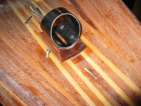
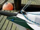
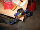
Finally, I found out what this triangular thing was,
installed on Bram's mast step. It's a Tack Tick Microcompass, so you can
track windshifts. Maybe in a few years...
Installing blocks
posted 2005 Sep 25
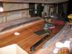
Installed a couple more blocks this week. These take time -
there's plenty of measuring, positioning, drilling, and preparation
before you can actually take the leap and install something.
First, I installed all the cleat bevel blocks. I had already
measured and positioned them; next I drilled pilot holes for
screws. I'm using four screws: three 1” #8 screws in the top,
and one 3/4” #6 at the narrow edge. Also drilled pilot holes in
the block itself.
Next, tape all the holes in the deck, and fill holes in the deck
and blocks with straight epoxy (so the wood sucks it up and makes a
tighter bond to the screw). Then, slather on some
epoxy/silica/404, then position on the deck and hold it down tight
while driving the screw from the underside of the deck.
I also bonded the pole launcher deadeye backing block into
place - forgot to sand the underside of the hull here (oops).
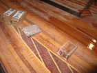
The next big set was the backing blocks for the spinnaker sheet,
and the bevel control blocks. The spin sheet I had to go out and find
a larger eye strap, to match up with the ratchet block - the block is
pretty sturdy and I didn't want the mounting to be sub-par. I then
drilled the holes (at a
slight angle; that seems to be what others are doing). The
actual backing block is a circular piece of bulkhead material, plus a
2" wide piece of the fibreglass/hybrid sheet. The fibreglass is very
strong - there's no way to pound a leg of the tee-nut through it. So
all the legs are flattened out.
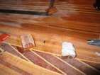
Next step was to drill holes for the centre bevel blocks. I had already
drilled the holes for the blocks so they were correctly placed; at
this point I just drilled through the deck. Next step was to put the
backing block in place and drill through it. Because these blocks are
right in the middle of the deck, you can't have a hand on top as well
as below - so I slipped the
block between the forms and the deck, and drilled there. Be sure
to write on the backing block which side is which, and which side is
up.
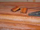
Getting ready to glass the bevel blocks in place. I cut away some of the station
so the screws had somewhere to go. I then sealed the holes. The first block was
the transom block - this
used 6-32 screws and hex nuts. I'm not sure this will work - it seems
like the nuts are too willing to slip out from the bond of the epoxy.
And you can't buy 6-32 stainless steel tee-nuts. Next up was the spinnaker control - this
used 1/4” bolts. Finally the bevel block. I installed
this and slid all the screws through so it was positioned correctly;
then I got underneath and fitted in the backing block one screw at a
time. Again I used the 6-32 hex nuts; I had to wake Tamara up to
drive the screws from the top while I held the nuts in place on the
bottom.
The screws I drove into the bevel blocks were lightly greased; the
ones for the spin sheet weren't greased at all. When I came back
seven hours later (couldn't sleep) and tried to move the spin sheet
screws, I found they were very tightly bonded in place, and
I was lucky to be able to get them out. Lesson: grease every bolt you
install when you're bonding these in.
[Update 2006 Feb 17: Now that I have
the deck and hull touching each other, I realized another important
point. These two bevel blocks should be positioned far enough apart
so that there is room for the centreboard
insert to be put in position. Keep that in mind...]
[Update 2006 Nov 14: There was a conversation
about how to best install the backing plates, and Bill provided this
wisdom (as Bill always does):
Steve,
I see from Bram's and others' replies that you have received some good
advice on how to proceed. As far as measurements are concerned,
locating the plates on the underside can be accomplished by using your
tape measure and T-squares on the underside of the deck. I also used
a laser level that has a sight for horizontal lines and a swivel
compass base to throw a straight line in any angle of 360 degrees.
The laser I used has the ability to cast a line on a curved surface as
long as the base is raised high enough above the arc to reach over the
crest and down the other side. This came in handy on the underside of
the deck when it was placed bottom-up on my stands. The deck is
supported by pieces of particle board, attached to the stands, that
are cut to fit the contour of the deck top. The laser that I used may
be available in Australia, so check www.strait-line.com for their
STRAIT-LINE Laser Level 120. Just be careful to measure twice and cut
once, as I goofed on the holes for the spin halyard RF30141 block and
had to drill the correct holes over by one inch. You can mark your
measurements easily with a black marker pen, as no one will see this
side when you are done.
When you place the backing plate centered where you want it, tape or
clamp it down on the underside of the deck, place the part you are
attaching on the backing plate in the correct position as if it was on
the deck. Drill thru the part, backing and deck, being careful to
slowly cut thru the s-glass to prevent delamination ( force of the hot
drill is against the underside of the s-glass). Remove the backing
plate and re-drill the holes to the size of the T-nut body. Install
the T-nuts into the backing plates after coating the drilled holes in
the deck and backing plate with some epoxy to seal the wood. I
attached the backing plates by sanding the underside of the deck
lightly around the installation points and applied epoxy/406 to the
backing plate. The T-nut holes were filled with heavy axle grease and
the machine screws lightly coated with the same, to prevent epoxy from
filling the hole. Install and clamp the backing plate by first
inserting the machine screws with large fender washers up thru the
deck and then lowering the backing plate onto the screws. Twist the
screw into the backing plate a couple of turns before lowering the
plate onto the deck, so that the holes will line up and the epoxy will
be prevented from entering the T-nut. Once the plate is lowered onto
the deck underside, proceed to tighten the screws from underneath and
you will have a nicely fitting and well-clamped backing plate. Any
grease that extrudes from the T-nut should be carefully scooped up to
prevent contamination of the backing plate. Any epoxy that oozes out,
can be used to seal the edges of the backing plates. Below is an
early picture of the set-up. Let me know if you have any questions
regarding the technique. Good luck.
Bill Scheumann
USA020 and USA040
]
[Update 2007 Jul 18: I also dug up
an article about how to best
mount hardware. One thing that's interesting from that article is
that the holes for the bolts are drilled out very large, and filled
back in again with epoxy. That may have been a better strategy than
what I did - time will tell.]
[Update 2007 Aug 01: I have to say, I
should have drilled the through-the-deck holes for the bolts a bit
larger than I did. I drilled them so the threads would just fit
through the hole; I should have gone up 1/32 of an inch in width. The
problem with the holes at the exact width is that the bolts tend to
seize in the holes - and getting them out is tough. If I drill, I
risk drilling into the nut or in the wrong direction.]
Installing the spin pole saddle
posted 2005 Sep 18
More positioning of blocks and drilling holes this week, and I
installed the spinnaker pole ring saddle.
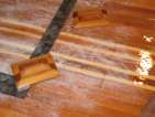
First, I positioned the bevel cleat blocks. I set
these up so they are centred at the exactly correct distance, and
point at the location where their lines come from - the fore block
points at the mast, the aft block at the bevel blocks in the centre of
the deck. The aft block has to be positioned just far enough away
from the step so that it's front edge doesn't interfere with the shock
cords exiting the toe rail (about 1" in my case).
I also positioned the centre bevel blocks.
Next up was to actually install the spin pole block and cheek
block. First was the cheek
block - it fits underneath the spin pole backing block. So: pound
in the t-nuts, remove, coat the hole in epoxy/silica/404 mix, coat the
inside of the t-nut in grease with a paperclip, slather the top of the
block in epoxy/silica/404 (leaning toward the 404), and you're ready
to go. I then used some cheap zinc screws covered in
grease to screw down from the deck top and hold the block in place
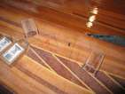
Next it's time to install the actual spin saddle. First, I had to
re-drill all four screw holes - the first crack I made the holes
parallel to the edges of the block. That caused the inner edges of the
heads of the flathead screws to stick out into the ring - which would
have torn up my spinnaker pole. So I re-drilled all the holes so they
came out the bottom of the block right next to the edge. Each hole
had about three exit holes - it took a bit to figure out the best
angle.
Were I to do this again, I would have taken the ring, passed the
screws through it so they were flush, and used the angle they came out
the ring to determine how to drill the holes in the block (duh).
I had previously soaked all those holes in epoxy, so they wouldn't
take on water. Now, I filled them with the epoxy/silica/404 mix,
slathered some on the bottom of the saddle block, and some on top. Roughed up the
bottom of the ring (which I bough from Roger at Aquilo Boats when I was in
Calgary). Slather a *lot* of filler in the middle of the plate. Pass
the screws through the ring and saddle block, and start screwing them into the
t-nuts on the other side.
Then it's just a process of adding in more filler until the entire
plate/deck space is full. Tighten up the screws, clean up the ring, and
that's it.
[Update 2007 Oct 15: I learnt at the
2007 Swift Regatta that this backing block should
really be much larger - one of the round pieces would have been
better, perhaps even with some of the high-load glass/hybrid backing.
Robert had to drill another inspection port through his bow because he
ripped this fitting out (gulp).]
Working on toe rails, installing hardware
posted 2005 Sep 11
I continued working on the toe rails this week.
- First, I routed the channel in the rail. I was going to do this
with a router table, but in conversations with Max he suggested I
just freehand it. So - freehand the groove all the way down the
end. tip: Watch out for the end where the router suddenly changes
resistance and wants to head off in strange directions. Also, make
sure to indent the groove at least 1/2" from the outer edge - the
width of a RF20711 exit scheve.
- Sand the routed groove.
- Mix epoxy/silica to light cream consistency (around 4
squirts), and splotch a bunch in the groove.
- On top of a sheet of plastic, paint 2" wide glass tape with epoxy
- Wrap the plastic around a spare strip (glass side out)
- Insert strip into groove, clamp in place, and allow
to cure.
- Once cured, apply to belt sander, and return to installable.
Next you make the strips to install in the bottom of the routed
groove.
- Plane down two strips to about 1/4" x 1/4". They should have a
slight angle - looking at the end you'd see an isosceles
trapezoid with the angle at about 10° off vertical.
- Seal them with epoxy.
- Bond them into the
channel - about 1/8" should be sticking out, and gets
sanded/planed off once
everything cures. You need quite thin epoxy/silica for this step,
very thin cream.
- When cured, sand everything back down, and the toe rails are
ready to go.
I also measured and drilled the holes for the
pole launcher cheek block,
pole launcher deadeye,
spinnaker retrieval block,
and placed the
cleat bevel blocks.
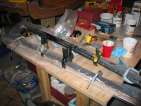
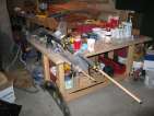
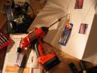
While all this was happening I also built a second shelf and rail on which to hang
clamps.
Rigging pictures
posted 2005 Sep 6
I was getting a bit confused on which blocks go where, so I
decided to pay Bram's boat a visit and see what was going on. He
has two - a VMG skiff and his own. I spent most of the time taking
pictures of the VMG - it represents the latest thinking on rigging.
Here's the pictures.
There are also a bunch of pictures which Bob Lewis took a while
back of one of Bram's boats. They're here. And don't forget the
other pictures of VMG's skiff I took in May. And finally, I took some
more pictures of the VMG when it was at Boats Afloat.
Preparing pole ring saddle
posted 2005 Sep 5
Started to install deck hardware. I'm missing the bolts I want for
the deck mounting - I want to use square drive bolts (call me a
Canadian). As it happens these are tricky to find in the US,
especially if you're looking for stainless steel. So I have to order
them.
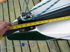
While I'm waiting for parts to arrive, I measured and drilled the
pole ring saddle. To ensure the ring was centred correctly, I
carefully measured the exact centre of the block and between the holes
in the ring, and then aligned up the mid-points. I also cut the backing plate; this is a
single plate, which will have plenty of filler when I actually bond
everything in place. I've seen pictures
where these are two separate pieces, but in a conversation with Bram
he recommended just one.
Page 35 of 62
« First
…
«
33
34
35
36
37
»
…
Last »