Spreaders, Boom, Rudder
posted 2007 April 30
Work progressed on a few different fronts this week. I managed to
get lucky and have almost an entire Sunday to work on the boat - not
a common event at all. (I'm not sure how I managed that...)
Spreaders
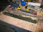
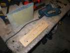
On the spreaders front, I took my new foam blanks, drew a line
along the chord, and cut
them in half. I had to sand down the inner edges slightly to
allow for the width of the sheer web I built. I
placed the saddles under a sheet of 2mil plastic sheeting (held in
place with spring clamps). I then cut the sheer web blank to the
right width and bonded them in place. The
best way to bond these (I discovered), is to place them in the
saddle, move them apart a bit, and syringe in the epoxy/silica, then
squish back together. Not much silica is required (too much spreads
out on the bottom edge and must be sanded off). Tape them (not too
tightly) and then place bags of warm water on top to clamp
them in place. Seems like a reasonable strategy.
Once cured, I removed the bags of water - but ziplock bags seem
to enjoy bonding to epoxy, so I got a bit of a wet bench. (hint: remove
the back on the ground, not on the bench, it makes a mess. Drain
the bags. &c.) The resulting spreaders have a bit of a bend
along the short axis - as if the leading edge didn't get pressed
down hard enough. I don't think this matters, but the effect is
there.
Then, I used the Dremel to sand down the extra
thickness of sheer web that pokes out of the top of the spreader.
While they aired out, I
set about bonding new
saddles onto my backing wood - my old ones are pretty beat up.
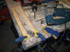
Once all that was ready, I plastic wrapped the
saddles (and taped the plastic in place), cut the fabrics, and layed
up the first spreader.
Once it passed the "tacky" stage, I pulled it out and removed the
mylar/peel ply (I was probably a bit late - it was probably 30
minutes too cured. Sorry. Fell asleep.) Place it in the saddle to
mark the trailing edge, cut, and place the
carbon/s-glass. I also painted in extra epoxy along the trailing
edge of the cut hybrid (under the s-glass) so there wouldn't be any
gaps - no trailing edge separation. A few hours later, the spreader
is done.
Next, spreader two:
- foam core, coated in epoxy/silica
- hybrid (scrap)
- s-glass (plain/coarse weave, from the centreboard/rudder
construction)
- peel-ply
- muslin absorbent layer
- mylar
Clamp and cure for
three hours. Then for the second step. Align in the saddle and
mark the trailing edge, cut it off (leaving a
bit of room), then:
- 1 1/2”
uni-directional graphite tape, three strands, one on either
side and one along the leading edge
- 3” uni-directional graphite tape, along the leading edge
- s-glass
(satin/smooth weave, from the deck/hull) pulled tight against
the leading edge. Getting this glass in place is tricky - it
wants to leave air bubbles. I squeegeed them out. In this
spreader, I used the syringe full of the epoxy concoction for
the rudder cassette to fill the gap. Run a finger along the edge
just to be sure before clamping.
- peel-ply
- muslin absorbent layer
- mylar
Clamp and let
cure.
[Update 2007 May 21: In
retrospect, I probably should have used less material in the skin
of the spreaders, since I did put the core in there. Next time, I
guess. They'll be indestructible.]
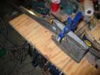
Mast and Boom
I wanted to get all the shaping and epoxying done on the boom.
First, I completed the third attempt at the
gooseneck tube. This one is about the right diameter - only a bit
of drilling is required. I also lightly sanded the epoxy/207 on
all the spars, so the varnish would adhere. The next step is to
tape the mast and paint it with varnish. Greg's suggestion was to hang
the past to find which side was heavier, then tape the top surface
(using 3/4” tape,
the width of the mast track). I held up the mast from both ends,
and allowed it to fall down the direction it wanted to. I then
marked the top on either end. Those are the endpoints. I wrapped the
tape around the top edge, unrolled it for the length of the mast,
and then lowered it on to the top surface. It stuck exactly where
it should have, very straight as well.
Just to verify that the tape was straight (beyond simply sighting
down it), I put the mast down into the groove in the garage floor. Bram
mentioned that the mast is a cone resting on a cylinder, and that
the tip of the cone aligns with the wall of the cylinder. I
confirmed this - the tip of the mast rests above the ground, and if
I flip it over, it rests on the concrete.
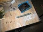
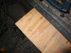
On the boom, the first step was to shape the leading edge. I
eye-balled the centre of the boom vertically, then used my ruler to
measure down 45° after leaving a 1” vertical at the top. I
drew the lines all the way around with a straight edge, but then
just sanded it down -
which turned out to not need as much removed as indicated. The boom
sands away pretty easily, be careful.
Then position the gooseneck tube (perfectly
straight), and press into a
bed of about 1/2” deep epoxy/silica and cut-up s-glass. I
sighted through the tube to make sure it was aligned correctly (or
as correctly as I could determine). Getting all the epoxy to sit
flat was tricky - because of the glass, it's hard to get a nice flat
surface. I'll sand it off once it's cured.
Next on the boom was to cut the trailing edge. This is supposed
to look like this  ,
where the tip is 1” high gradually increasing to 1 1/2”,
then the radius starts. The radius ends about 3” from the end
(Bill used 4”). Mine didn't quite turn out that way (I
should have held the boom *up* off the floor, not let it rest on the
floor, what was I thinking?) but overall I'm happy with the result.
With that cut, I filled the end with epoxy/silica/chopped s-glass
(and held it all in place with a bit of tape.)
,
where the tip is 1” high gradually increasing to 1 1/2”,
then the radius starts. The radius ends about 3” from the end
(Bill used 4”). Mine didn't quite turn out that way (I
should have held the boom *up* off the floor, not let it rest on the
floor, what was I thinking?) but overall I'm happy with the result.
With that cut, I filled the end with epoxy/silica/chopped s-glass
(and held it all in place with a bit of tape.)
Once that cured, I rasped the top to get it
flat, and since I had a bit of black with 207 left from the
cassette, I painted it on top of both ends of the boom filler (a
bit of extra UV protection).
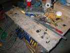
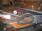
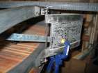
Rudder cassette
On the rudder, I decided that I wanted a bit stronger bond
between the tiller and the rudder cassette. So I put three layers of
unidirectional carbon running from the tiller to the cassette, and
then a layer of carbon
sheet over top. This should help with tensional stress, and keep
everything in place.
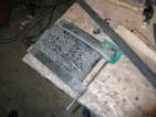
With that cured, I sanded, then applied filler, using the recipe
three squirts epoxy/207, three tablespoons of 407, and 1/2
tablespoon graphite. (And with some of the excess, I filled a hole in the black on the
deck.) Come back three hours later and repeat.
[Update 2008 Feb 25: The cut at the
end of the boom should allow the large 3-series floppy block which
gets mounted there to move freely side to side, and hit the edges of
the boom with an offset of about 60° from hanging straight down.
The block gets installed with it's outer edge about 1/8” from
the end of the boom. When I bonded the outhaul rack on, I trimmed the
boom to be slightly shorter, and re-carved the trailing edge.]
Bond the tiller, begin the spars
posted 2007 April 23
Rudder cassette/tiller
Bonded the tiller to the cassette this week. I cut my (ragged) plastic from the top
of my bench, and then positioned the tiller assembly on the top. I
considered building a jig, but figured this would work as well. I
drew a straight line along the bench top. With the tiller in the
boat, I made sure it cleared *both* rails and outlined the position on
the cassette and clamped the tiller end at that position. I then
removed the cassette and tiller assembly from the boat (being careful
not to get it out of position), flipped it over, and positioned the assembly on
the bench top so that the cassette top was flat on the bench and the
tiller handle just touched the edge of the table. Draw a line to show
the edge of the cassette, and draw the cassette outline. I also drew
a couple ticks on either
side of the centre line at the edge, so I could centre the tiller.
They correspond to the exact outer edge the tiller should fit
between. Yes, there's some parallax error, but not a lot.
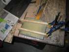
Down to business. Clamp
the rudder box in place in it's outline. Grease/vaseline the
pintle, and place the roughed-up nylon inserts in place. Mix up a
whole whack of epoxy/206/silica/407, force it into the end of the
tiller, and slide it
on. The tips of the U cut in the cassette end of the tiller rest
against the edge of the wraps around the cassette, so if it touches
the edge of the table and the wraps, it's correctly positioned. Once
it was positioned, it took a bit of time to clean out excess epoxy (or
add more) and get decent fillets.
Unfortunately, 206 hardener and a cool garage didn't do enough to
slow the reaction inside the tiller. Uh oh. Thermal expansion. Crap.
More than that, the tiller was hot to the touch as well. (When I was
drying out the inside of the tiller after melting the foam, I used a
blow-dryer - and I knew that if the outside is hot, the inside is very
hot.) Having to rebond, or rebuild (gulp) wasn't going to be a good
thing. So I bagged a bit of ice-water, opened the garage, and hope hope hope. (I didn't
sleep well that night.)
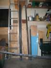
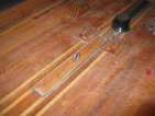
Spars
I also began preparing the spars for their work. First, clean with
acetone. Next, a very
thin application of epoxy. I followed Bram's
directions for this: roll a line on one edge about 1/3rd of the way
down the mast (I used a trim
roller from the Orange Borg for this), then go back and spread the
line out around the entire mast. Repeat for all the other spars. To
cover the entire area took about five squirts. I had a tiny bit of
epoxy left over, so I coated the tiller. I had to return and
touch up a couple of
places on the mast and boom with another coat of epoxy. But that gave
me an excuse to coat the base of the mast, which I missed and didn't
sand or coat the first time around.
I began shaping the spreaders to attach to the mast. Draw a long
line (to align the mast) and a shorter line at 90°. I decided to
use a collar, and so I slid it down. The centres of the spreaders
where the shrouds pass through should be exactly 30.5” apart (per Greg, via the list).
Equivalently, the leading edges of the spreaders should be 19”
long (per Bram). Before I knew it, I had gone too far: the distance
was going to be too short. In mail with Bill:
Bram's finished length measurement is 19" from the longest point on
the leading edge. My shroud bushings are centered in about 3/4" from
the ends.
Greg's suggestion is a string 30.5" long between the shroud holes and
6.25" from a straight edge, laid across the aft side of the shroud
holes, to the mast track. If you are on the lighter side and need a
softer mast, 32.75" and 6".
I hollowed out 2" and filled it with epoxy filler when attaching it to
the collar and making the fillets.
To attach the spreader collar to the mast, I used 4 3/16" x 1/2"
grip length rivets.
Drat. I'll have to rebuild the spreaders. But that means I can
use Greg's suggestion and build a sheer web on the inside:
- Basically take a long enough strip of some of the spare hybrid
or carbon plate you used for the mainsheet platform to construct the
shear web. Cut the shear web just thicker than the spreader.
- Make a cut down the centre of the core.
- Sandwich the strip in there with some peanut butter and wrap the
spreader arm with a few windings of saran wrap strips 2 inches wide.
- Place in the lower saddle and tape or weight it down. Warm water
in a sealed plastic bag is good.
- When set come back with dremel sanding drum and sand off the
excess strip poking up on top of the foil, then skin as usual.
In preparation for this, I assembled my hybrid scraps (many of which
would have been thrown away otherwise) and bonded them together. Just
have to wait for the blanks now.
Gooseneck
I also set about to build a tube for the gooseneck. These are
pretty easy: I taped mylar around a 1/2” dowel, then wrapped it
in glass then hybrid.
Roll it up with epoxy, and it's ready to go. But my first attempt I
couldn't get out. Second time, I didn't tape
the mylar to the dowel, but the opening was too large. Third time, the mylar is
just tightly wrapped around the dowel, and taped in place. And the
dowel is 7/16” (and with the width of the mylar, should be about
right).
Preparing to bond the tiller
posted 2007 April 16
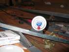
Prepared to bond the tiller to the cassette this week. My first
strategy was to clamp a metal
bar to the cassette with everything in place, and then adjust it
to be the correct hight. I figured I would measure the angle, then transfer that to
the tiller and bond it in place.
Next up was to actually cut the vertical hole in the tiller
to fit around the cassette. (I decided the bottom of the tiller would
be the side with the small
ridge where the layup squeezed out of the tiller saddles.) Of course,
the jigsaw cuts on a slight angle (sigh, again) so it wasn't quite
vertical and will take a bit of cleaning up. I probably should have
left more material on either side, and cut a slit a foot into the
center of the tiller, so there would be more bonding area on either
side of the box. Overall it seems pretty good.
Cut complete, I melted
some of the blue foam from the inside of both ends of the tiller with
acetone (and water to stop the melting), and poured in a bit of epoxy to seal up the hole
(once everything had dried up). With a bit of the extra, I mounted a shim on the upper
rudder gudgeon block to make things more vertical.
Finally, I cut a few supports for the mast in to
prepare to bond the spreaders to the collar.
Sanding the mast
posted 2007 April 9
Did two things this week: installed the rudder box, and sanded
down the mast/boom/spin pole.
Rudder box
Installing the rudder box was pretty straightforward. The box
itself is all ready to go (the pintle fits perfectly), so I just
had to install the top rudder gudgeon on the transom bar. So:
- Level the boat itself. I put a metal bar across the
transom just in front of the transom bar and centred it between the
gunwales. Put a level on top, and level the entire boat.
- Then, install the lower gudgeon, slide the pintle through the
top and bottom gudgeons, and align them vertically.
- Drill holes for the
bolts. I shimmed the lower edge because the top gudgeon backing
block tilts in slightly. Even do, the hole I drilled was dead on.
- Next, seal the holes
with epoxy. I put tape on either side, then filled a syringe and
squirted it in the bolt hole from either side. Wait about ten
minutes, continuing to fill the holes as any air pockets form. Once
ten minutes is up, pull the tape off, push a bolt through to remove
the excess epoxy, wipe clean, and walk away. (While I was waiting,
I cut a shim for the
top gudgeon.)
- Once it's all done, celebrate!
I was originally going to put tee-nuts on the inner side of the
transom bar (others on the list have done this). But then I figured
it wouldn't be pretty, and the bolts would be a bit long, and I'd
probably scrape myself up as I passed by them. Instead, I put the bolt head on the inner edge
and nylon nuts in the
gudgeon plate. The nuts interfere with the rudder slightly if it's not
all the way down, but it shouldn't be too big a problem. This way, I
can at least try this out and see if I like it, and can always go back
to the tee-nuts if necessary.
Sanding Mast/Boom/Spinnaker pole
Next was to sand down and prepare the mast for re-applying the mast
track. This has come up on the list a few times
(here,
here,
here)
and I mention it in my worklist for winter.
In conversations with Greg and Bram, they also added a bit of colour
to those descriptions:
- remove track, sand down mast. Can sand past the dimples on the
mast; there's vertical CF strands on the inside which are wrapped
with a layer of cotton-thickness mesh fabric
- sight down to get the position; hold like pool cue and verify
bend
- hang from two points in ceiling - mast will fall down so track
side is up (if mast bends, want track on side it bends toward)
- place on floor, mark bottom point on both ends; this should be
end-point of track
- place strip of tape down center, width of track
- paint on perfection varnish (2-part linear polyurethane) -
perfectly clear, shiny
- rip tape off, now have line where track should be
positioned
- mix plexus up in coffee cup (not plastic)
- use mixer stick to place plexus along track edge
- move entire track onto mast, press into place
- don't press plexus all the way down - plexus likes to fill
gaps
- put tape along outer edge of track, place track, pull tape
up
- sight along track to verify it's straight, adjust if
necessary
- tape over track to hold in in place while plexus sets
Bram recommended a similar process:
- coat mast with really thin epoxy
- four squirts, use 207 hardener, use thin 3" roller
- tip red cup on side, roll roller around edge to get even spread
- roll along top edge of 1/3 of entire mast
- then go back and roll around mast
- should be shiny, but no more
- sand, put 3/4” tape down where the track should go
- put down tape adjacent to 3/4” tape, rip up 3/4”
tape, sand down the "gap" in preparation for the Plexus
So first up was to sand everything down. I bought my mast from
Bram a while ago, I have a
sectioned mast (one of the early designs). I had to remove the mast track. Polypropylene
doesn't stick well to much anything, and the 5200 adhesive that Forte
used wasn't effective. (Although I sighted down the track before
removing it, and it looked pretty straight to me...)
So, I popped the track
off, then cut off the
remaining adhesive. Loaded up 40-grit on my random orbital sander,
and had at it on the spin
pole, to see how it went. In two passes, I hit most of the surface. While
I was at it, I roughed up
the underside of the mast track - it was perfectly smooth, which can't
assist bonding much.
Finish up with the boom and mast and call it a week.
More work on the rudder box
posted 2007 April 2
The next step on the rudder box was to put the straps in place on
the top and bottom edges. First, I cut the jigs - two layers of wood
stacked on top of each other and screwed together (so both pieces are
the same). Then drill the hole to position the
pintle. I found the spot by putting the gudgeon blocks flush against
the outer edge of the rudder box with the pintle hole centred on the
centreline and with the gudgeons aligned at 90°, as if I were
sailing straight.
Test. One other
problem with these jig pieces was that the hole was cut at a slight
angle - that's just what jigsaws do. If I had used the bandsaw this wouldn't have
been a problem - but it was stuck in a corner of the garage. (Ah, for
more workspace...) Instead I just rasped out some of the inner edge,
and flipped them over and removed some that way.
Next I finished up the rudder box. I decided to try and address
the "crack" I heard while removing the rudder - if that crack was
parts of the box letting go, well, that wouldn't be good. (Greg's
comment was this:
For example, here's a story, you're training, you're tired, its cold
in the water and you don't want to get wet, you have discovered
something when going downwind in 14-16kts with very sharp stabbing
gusts (those you get with a shore breeze and cold water). Discovered
that in the lulls you are tea-bagging and getting your ass wet but
that sharp steering can hold you up using centrifugal forces of the
turning boat and steering up into the wind to get more
pressure. When the inevitable stabbing gust hits you're way too high
and still don't want to get wet. Steering down as the boat loads up
will take more rudder out of the water with the heal of the skiff
making it less effective so you steer down more. Now you have
accelerated to 15kts or more and are dragging the stalled rudder
through the water sideways with the tip 24 inches only in the
water. But hey you didn't have to get wet, right? Either the cassette
or your gudgeons don't break, or they do. Either way the cassette
gets a huge torsion load. We had a lot of the 49er rudder cassettes
go at that point long the back edge of the cassette.
) I took pieces of carbon fibre about 6” wide, put them over
the leading and trailing edges and pulled them at an angle (so I had
6” thick bias tape, essentially), and then wrapped the entire
thing in another layer of
carbon. May it hold when I'm tea-bagging.
I had to fill and
re-drill the holes for the rudder — the holes for the pintle
were too close to the leading edge of the rudder box (drat). When the
rudder was fully turned, I could only go to about 45°. They're
now significantly further
from the leading edge. I verified that they were aligned along the length of
the rudder with a long steel bar (and a bit of filing).
Time to get going. I had bought some nylon sleeves at HD/Lowe's to
allow the pintle to rotate (Christian talked about this here,
but he used carbon sleeve and epoxied it in place over the pintle,
then bonded the tube in place). I roughed up the outer surface of the
nylon inserts and applied a thick layer of vaseline, so the pintle
doesn't get stuck in there during bonding. Tape, and we're ready to go.
The actual taping took
about 45 minutes. The wraps are a number of layers: 1) 3 wraps 1
1/2” unidirectional carbon fibre tape, 2) (roughly) 4 wraps
2” s-glass tape, 3) 2 wraps carbon tape, 4) one wrap glass tape.
All of these I "interleaved" the last half of the wrap between the
last layer. I'll probably sand off the extra 1/2” of tape top
and bottom (I have to in order for it to fit between the
gudgeons).
Next up: fill the hole between the tape, leading edge, and the
nylon inserts. I cut a dam from matte board and covered it with
packing tape, then taped the dam onto the bottom of the hole. Then fill with epoxy, silica,
graphite, and cut up pieces of carbon. I pressed it all in with the
end of a pen (and fingers).
Page 16 of 62
« First
…
«
14
15
16
17
18
»
…
Last »